In this post I have explained how to build a few interesting LED circuits, and also learn how to connect LEDs correctly in a circuit.
LED stands for Light Emitting Diode, which is actually a semiconductor diode which has the property of emitting light, when current is passed through it in the right direction, or when the LED is forward biased.
An LED has two terminals for connecting to an electrical circuit. Since, an LED is basically a diode, its terminals have polarity in the form of anode and cathode.
The anode terminal is supposed to be connected with the positive supply, and the cathode to a negative supply.
Mostly, the maximum voltage an LED can tolerate is 3.5 V, however 3.3 V is the optimal value that is recommended for most standard LEDs.
LED Resistor
Although an LED is a diode, it's highly sensitive to current, and cannot tolerate anything exceeding its specified range.
In order to ensure that an LED is safe from an over-current situation, a calculated resistor is normally added in series with one of the terminals of the LED.
This resistor may be connected in series with either the cathode terminal or the anode terminal of the LED.
This current limiting resistor can be simply calculated using the following formula:
R = Input Supply - LED Voltage rating / LED max current.
For example let's say an LED has a forward voltage rating of 3.3 V, and max current limit of 20 mA (0.02 Amps), then assuming the input supply is 6 V, the value of the series limiting resistor can be calculated as follows:
R = 6 - 3.3 / 0.02 = 135 ohms, the nearest safe available value being 150 ohms.
How to Connect an LED
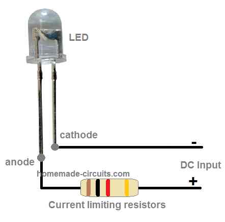
Connecting an LED to a supply DC, for getting an optimal illumination, is very easy.
A simple connection diagram can be seen in the following image, which is applicable to all LEDs.
The current limiting resistor must be calculated as explained in the above paragraphs.
Here, the shorter terminal which is the cathode goes to the negative supply input, while the longer terminal which is the anode pin of the LED is connected with the positive input of the DC supply through a limiting resistor.
Application Circuits
LEDs are fascinating devices since these are able to produce powerful light output in different colors, as desired by the user for a given application.
LEDs can be used for making plenty of eye catching ornamental or indicator circuits for many useful purposes.
Without further ado, let's take a look at a few interesting LED application circuits as presented in the following paragraphs.
Smallest LED Flasher
Flashing LED indicator look very attractive but the design can be more interesting if the circuit uses the least number of parts.
The following circuit shows how a single LED can be configured with a single transistor to create a reliable flashing LED indicator.
For more information about this circuit you can refer this article.
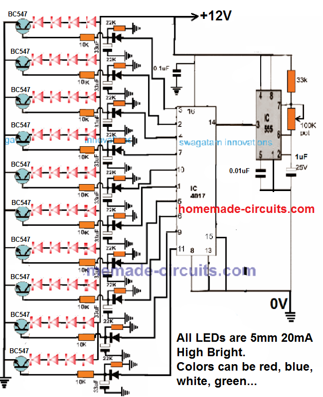
Random LED Flashing Light for Christmas Tree
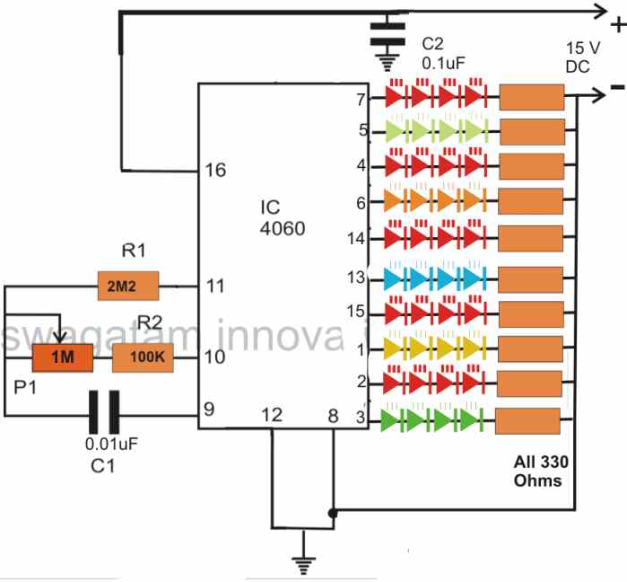
The best use of LED devices is their ability to decorate anything as desired by the user. The following circuit shows how a single IC 4060 could be used for building a multiple LED flasher circuit as shown in the following diagram.
All the connected LED strings will flash and twinkle at different random rate depending on the adjustment of the P1 pot or the value of the capacitor C1.
It is used for decorating a Christmas tree or applied for making a twinkling LED necklace around an idol.
Full description of the design is provided in this article.
LED Rotating Light
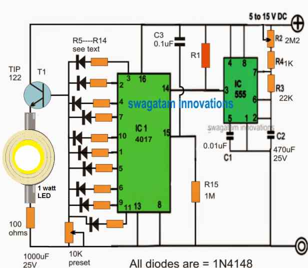
If you are interested to build a rotating police or ambulance light effect without actually using a rotating mechanism for the lamp, then the following circuit can help you.
The LED used in this circuit is a 1 watt LED which will generate a slow alternating bright illumination and fading, producing a rotating LED light effect.
More information about the circuit can be found in this article.
LED Back light Nameplate
The following image shows an example of how an attractive back light illuminated LED name plate circuit can be built using just 4 LEDs attached horizontally at the 4 corners of the nameplate, internally.
More information on this and the full building procedure can be read in this article

LED Cube Circuit
To build a LED cube light you will need a plastic cube, a bunch of LEDs, and a cascaded delay circuit.
For each LED a two transistor delay ON circuit is used, and many of these delay ON circuits are cascaded with one another, depending upon the number of LEDs, to form a long delay chain, looped from end to end.
When power is applied, the LEDs begin switching ON one by one until all the LEDs installed on the cube are lit up.
After all the LEDs are lit up, the reverse happens, and the LED turn off one by one, and the cycle keeps repeating.
The details of the circuit can be found in this article

Water Level Indicator
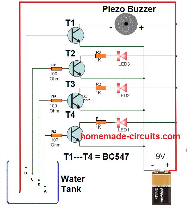
LEDs can be also used for indicating the level of water in a water tank. For this we need a handful of LEDs some transistors, and resistors. The complete design can be seen in the following diagram.
When the water bridges the contacts (A to D), between the transistor base resistors and the positive supply, the respective LEDs illuminate in succession, indicating the rising level of the water.
More on this can be learned from this article.
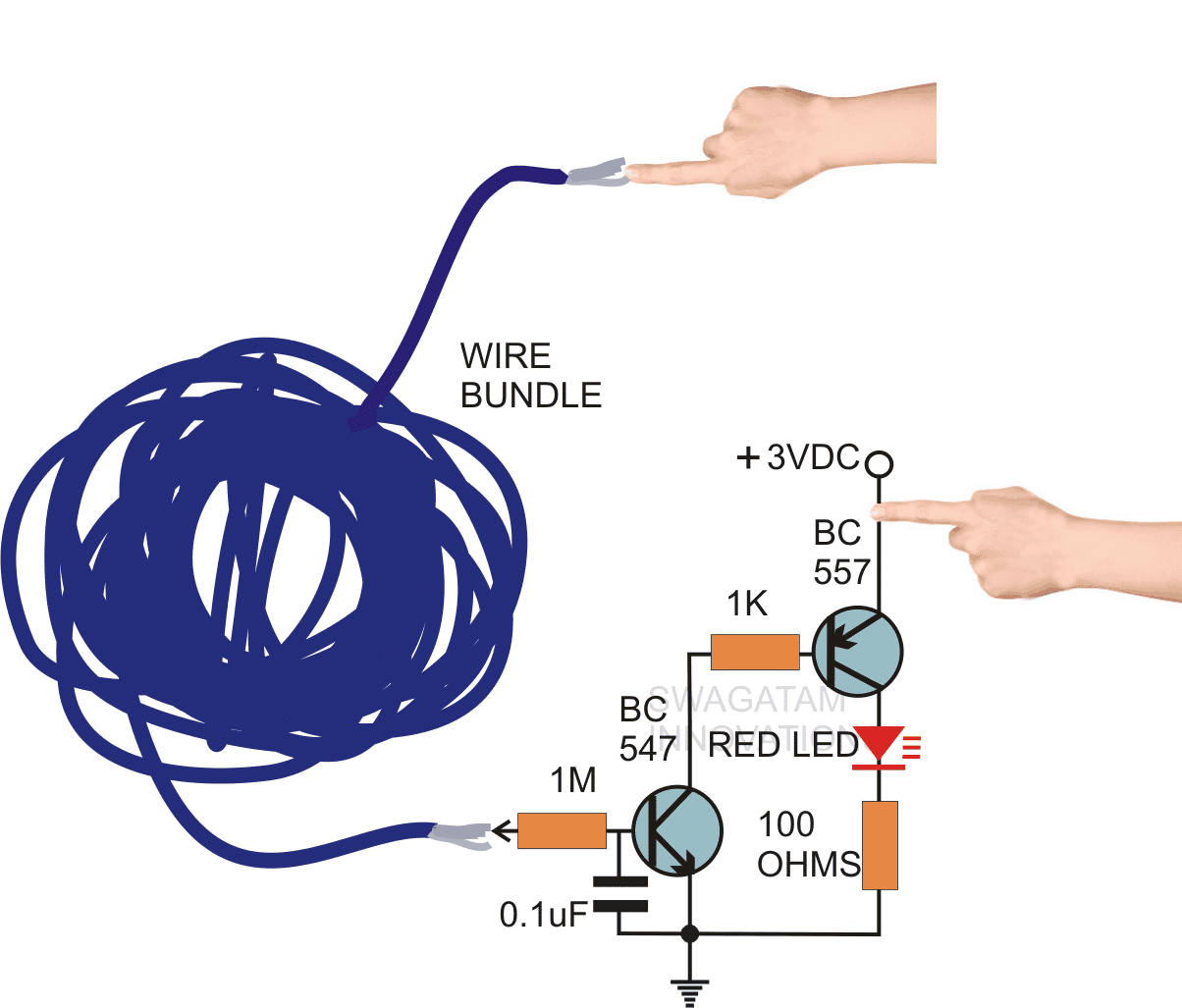
Simple Continuity Test
Just a couple of transistors along with an LED is all that may be needed to make a simple continuity tester circuit.
This circuit can be used for testing the continuity of transformers, wire bundles, or any electrical system having complex wiring system.
In this continuity tester configuration, when one end of the wire bundle is touched with one hand and the other hand held over the positive supply, then touching the 1M resistor end with the other end of the wire indicates the continuity of the wire bundle
More on this can be learned through this article.
In the above article I have explained a few interesting LED circuits, but this might be just the tip of the iceberg, since there are innumerable more circuits that can be designed using LEDs for getting fascinating lighting effects or for useful indication purposes.
If you are interested to investigate more LED circuits, you can refer to the following link:

Questions & Answers
buen dia
deseo me colaboren con el esquema de un circuito con Leds ( entre 100 y 150) para un aviso luminoso, usando el 4017 y 555 en cascada. Gracias
Sure, please also specify the operating voltage and how the LEDs are supposed to sequence?? I will try to figure it out…
Hi – I have an intercom that I want to add a mini led light on that lights up when the talk, listen, and door buttons are held down. I am really not handy to do this myself but have no idea who to look for locally to do it. I’ve checked with intercom repair, hobby shops, electronics repair, and no one does this sort of thing. Do you have any suggestion where I should try to find someone? Thank you.
Hi, I can help you with this, but i will need to see the full schematic diagram or the wiring details of the intercom, only then I can suggest.
Here is the electronic part. I removed it to paint the face of the intercom.
Actually i will need a schematic diagram, so that I can see the internal wiring of the components, then I can suggest you where the LED needs to be connected.
In the meantime you can try the following quick remedy which will help you to know whenever the intercom becomes active:
Hi – I’m sorry, but I don’t understand any of this and I don’t know where I would get a schematic. I’m trying to figure out what I would search for online to find someone in my area to help me with this. Is it an electrical engineer? I just get huge companies when i search that. Intercom repairs don’t work either. I really need to find someone I can take this to for help. I just want to add an LED with a battery that will light up when a button is pressed. I have a laser toy for my cat that does this so I know it’s not that hard. Thanks.
If you need a simple power ON LED indicator, in that case you can simply add an LED with a series 1k resistor across supply terminals of your intercom board after the switch, that’s all.
If you have any electronic technician in your area, you can ask him to do it, he will be able to fix it quickly.
Greetings Swagatham. I am looking for a circuit as follows/ Using easily available ICS and components from nearby neighborhood component shops.
A) Its basically 3 Strings of LEDs of X and X being minimum 10 and upto 16 (whatsoever you advise)
B) Bulbs numbers as 1 to X
C) String A – Bulb 1 Lightens up first then after 1 sec bulb 2 lightens, then after 1 sec bulb 3 lightens up, and until all lights in string A lighten up.
D) Once all are lighten up in string A, then first bulb of String B lightens up.
E) after 3 sec all bulbs of String A switches off.
F) now the series in step C repeats one by one all bulbs glowing in string A.
G) Once the complete series in String A lightens up the Bulb 2 of String b lightens up
H) after 3 sec all bulbs of String A switches off.
I) the step C repeats and then the bulb 3 of String B lightens up. This continues until all bulbs of string B lightens up.
J) then all the bulb 1 of string C lightens up.
K) the series of steps in above repeats and then bulb 2 of string C lightens up.
M) likewise all bulbs will lighten up in String C – one by one and then the entire will stop glowing for 1 sec.
N) the cycle will repeat once again
O) the timing on the above steps is only indicative. facility to available for increasing or decreasing the interval of light glowing.
Can you please help me with the circuit of the same. Also can you make and supply an assembled circuit?
Thank you D H Sanj,
The procedures you have mentioned can be implemented only through a microcontroller such as Arduino, and unfortunately my Arduino knowledge is not good.
So, I am sorry, I may not be able to help you with this project. I really wish I could do.
Making this circuit using discrete components can be actually very difficult and bulky.
Hi Swagatam,
First of all thanks for providing all this information on your site which is most helpful!
However, I just want to double check something before I break my ‘project’.
I have 24 so called tea light shaped christmas LED lights which were all powered by one 3V CR2032 battery.
But I actually want to get rid of the batteries since 24 are a lot of them! So I thought I connect all tea lights in a string and then power it with a DC adapter.
I discovered it is not that easy as I already thought.
So I know I need a few resistors because the lights will not be powered by a battery anymore. This will make the current flow more stable, is that correct? (I understand it does more than just that, but in a simple way let’s say)
And I was thinking to use a 12V power adapter, but then I need a combination of parallel and serial connections, correct?
If that is the way to do it, would it then be possible to create one string with the parallel/series combination, or do I need to connect all strings in series directly to the power adapter?
So the question is basically if I can create 1 long string using the parallel and serial connection method?
I hope I explained it clear enough, but if it isn’t just let me know what more info you need.
Thanks in advance.
Best regards,
Vince
Than you Vince,
12V can support 4 LEDs in series if the LED froward voltage rating is 3.3 V max.
So you can make 6 strings of 4 LEDs each and then connect them in parallel.
You can also include a series 22 ohm 1/4 watt resistor with each of the strings just to make it safer for the LEDs.
Thank you very much for your quick response Swagatam! Much appreciated!
This confirms my thoughts about this, so that’s how it’s going to be.
I’ll let you know when it’s finished.
Cheers,
Vince
Sure, no problem Vince!