In this post I have explained how to illuminate an LED using wireless power transmission.
Wireless Power Technology
Wireless power is an emerging technology in this present world. But the stunning fact is that it’s a century old concept. This concept was emerged by Nikola Tesla.
Charging batteries through wireless power is used in many high end Smartphones, electric cars, electric toothbrush, and wearable electronics like smart watches and so on.
The major problem of wireless power transmission is the efficiency. Today’s gadgets that utilizes wireless power has terrible efficiency, it can only receive 1/4th of the transmitted power.
Rest of them dissipated as heat and some lost as magnetic field. The range between transmitter and receiver is very short, at a range of few centimeters.
Before going for circuit diagrams and explanations here are some common myths people might think about wireless power transmission. Some people think that it is a dangerous protocol that will kill or injure you.
The fact is that, the power is transmitted in the form of pulsating magnetic field which won’t harm you and not electricity itself transmitted.
Some people might think, it says wireless so; it can be transmit power over a huge distance like radio waves. But that’s not true, wireless power utilizes nearly the same principle as transformer, but at high frequencies and without core.
However both the transmitting and receiving coils must be close as possible to achieve greater efficiency.
Circuit Operation
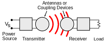
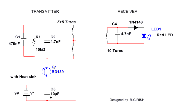
The proposed setup for illuminating an LED with wireless power transmission consists of transmitter and receiver circuits. The power is transmitted by 5+5 winded coil which is coupled with 4.7nf capacitor.
The receiving coil consists of 10 turns and also coupled with 4.7nf capacitor.
The coil diameter is around 5 cm both. This 4.7nf (C2 & C4) capacitor is responsible for efficiency, if the value is mismatched, for example: transmitter coil coupled with 10nf and receiving coil coupled with some other value, you may not get the correct result.
This is because the transmitting and receiving coil has resonant frequency.
Both transmitting and receiving coil’s resonating frequency must match.
The transistor BD139 should be mounted on a heat sink. C1 and R1 are oscillatory components which generate frequency in combination with transistor.
The frequency spikes are applied to coil, which generate alternating magnetic field around the transmitter coil. This field is picked up by the receiving coil and rectified by 1N4148.
Preferably use a germanium diode with low forward voltage drop, otherwise a common diode like 1N4148 might also work. Use a red LED because some red LED has low forward voltage than green or blue colors, but other color LED will also work without any problem.
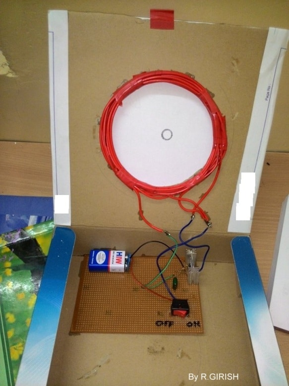
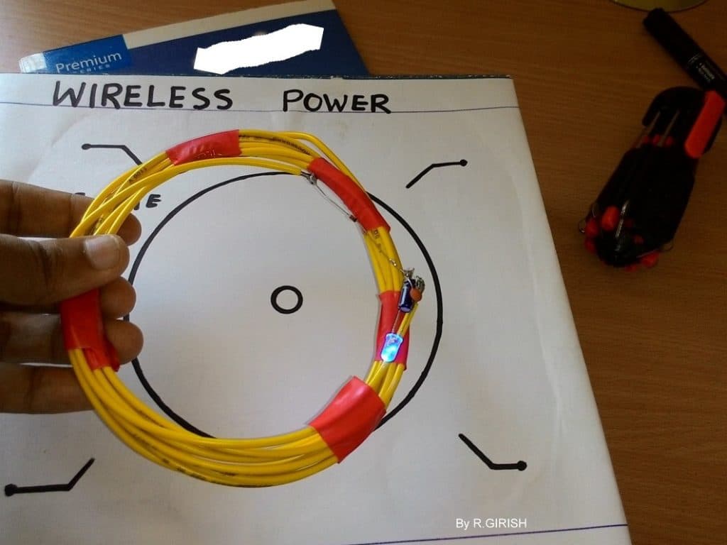
The coil can be made from electrical wire that lying around your house. See the prototype to get an idea on the coils.
Prototype Image of Wireless LED Lamp


Questions & Answers
Hi, Swagatam,
What’s the lowest voltage I can use with this circuit, and what do I need to turn the LED on at 60 cm of distance?
Merry Christmas and Happy New Year.
Nelio
Merry Christmas to you Nelio,
Those parameters can be fixed only through a practical trial and error test, it can be difficult to judge without giving it a practical testing…
the 1N4148 is not a germanium diode.
Yes, it is a silicon diode, the article was submitted by an external author.
There’s a project I want to work on but I’m running into some difficulties. I’m not 100% following how to build the transmitter and have purchased a couple of already made ones. The difficulties I’m running into is the limited distance between the transmitter and the led is maybe about 50mm too short to get the ideal brightness of the led. The transmitter coil can’t be too wide as I’ll be putting it within a base that will hold a resin sphere with the wireless led inside. Would you be able to just extend the range upwards if you had more turns building upwards instead of outwards with the wire? So instead of having a 200mm diameter transmitter coil, have the coil diameter about half but still use the same amount of wire just adding more turns.
I guess the diameters of the transmitter coil and the receiver coil must be identical. You can try more number of turns but the more important thing is the input current and voltage to the transmitter, you may try increasing the voltage and current to the transmitter for increasing its range.
I’ll definitely try increasing the voltage. That method seems easier. Thanks!
Dear Swagatam, can you please describe the primary coil in a little more detail? How to wind it and what kind of wire will do?
and when I made the circuit my Led in secondary coil doesn’t glow steady, it only blinks once when I connect power supply. Meaning, some form of PWM input in place of the battery will give it a steady glow… am I doing anything wrong which is causing this?
Hi Prithwiraj,
The primary coil is a continuous 10 turn coil with center tap after 5 turns.
No external PWM is required, because the transmitter circuit is a self oscillating circuit using a feedback.
The center tap is connected with the positive of the battery.
Try to build the coil exactly as explained in the article and connect the battery positive with the center tap.
Thanks for responding as always. I was not making a continuous coil, that was the reason probably it was not working for me. Let me make the coil exactly as you described. Will let you know if it worked.
Sure, no problems.
I remember I thought of such a system when I was about 12 years old (1972 ) it was a science project at school.my idea was to have an electro magnet coil on the beach and a similar coil in a light house at sea . So that you could do away with the power wires ! Don’t think the teacher was that impressed .????
That’s because you weren’t thinking big enough, You should have suggested placing an unshielded proteum, deuterium, tritium mix fusion core at about 8 light minutes from the Earth and installing cuprious-oxide passive radiation conversion modules (it was the 70’s) on the light house to charge a massive electrochemical storage matrix for 24/7 operation.
The most difficult part is zoning. 😀
Very interesting, the concept still remains unimpressive to date….
What if i make coil diameter 2 to 10 times bigger will the transmitter and receiver work between a higher distance? And what if i increase the value of the capacitor respective to coil diameter will this changes follow the same principle as the former circuit?
Optimizing diameter and capacitor won’t help to increase the range. The air or the atmosphere in between creates a high resistance as it increases between the Tx and the Rx, and to cope up with this resistance we have to increase the input current…and thus the system keeps highly inefficient as the distance is increased. so it looks impossible no matter what improvement you do.
I am using 9.1 pics farad of capacitor at both TX and RX ends. Tell me what is the operating frequency.
Here’s the formula:
f = 1 / 2π√LC
My operating frequency is 700 mhz and 300 mhz. Will it work at these frequencies?
According to me it may be impossible to transfer power in the MHz range.
I have designed the system at these frequencies but now i need to light an LED.
MHz frequency cannot pass through such long coils, the equivalent coil may be a cm long wire, so I am not sure how a cm long wire can transfer wireless power to illuminate a LED.
CAN I WIERLESS RECHARGE MY DRONE JUST BY LANDING ON A PAD WITH TRANSIMITTING COILS.??
yes that’s possible!
I didn’t understand the 5+5 turns …..plz explain … Is there two wires used or two seprate coils each having 5 turns ….
Also u said that the diameter of coil is 5 cm but in picture is looks very big…. Plz explain i want to build this
5+5 refers to total 10 turns with center tap after the 5th turn, yes the 5cm value seems to be a typo, it should be 15cm according to me, or you can roughly estimate the value by comparing the 9V batt with the coil as shown in the image.
hello girish ,
whether i can this power from transmitter to desired receiver, if i have 1 transmitter and a 4 receiver by making any modification.
Hello Davis,
Use thick copper wire for coil construction, you may use electrical wires which is used for home wiring.
If you use thin wire, of course it works but you must reduce the distance between transmitter and the receiver.
Regards.
helo sir ,does any wire work for the coil