• Skip to main content
  • Skip to primary sidebar

Homemade Circuit Projects

Need circuit help? Post them in the comments! I've answered over 50,000!

Blog | Categories | About | Hire Me | Contact | Calculators-online
You are here: Home / Inverter Circuits / How to Interface Arduino PWM with any Inverter


How to Interface Arduino PWM with any Inverter

Last Updated on August 3, 2020 by Swagatam 8 Comments

In this post I have explained how to interface an existing Arduino PWM signal with any inverter to convert it into a sine wave equivalent inverter. The idea was requested by Mr. Raju Visshwanath

Table of Contents
  • Technical Specifications
    •  UPDATE:
    • The Design
    • Circuit Operation

Technical Specifications

I am in need of following inverter circuit designs:

Single phase DC to AC inverter. Input 230 VDC. PWM signals will be sent from Arduino Uno.

Three phase DC to AC inverter. Input 230 VDC. PWM signals will be sent from Arduino Uno.

Can you please let me know your estimated service charges, lead time and payment terms?

Thank you,
Raju Visshwanath

 UPDATE:

Please also refer to this article which explains how to build a simple pure sine wave inverter circuit using Arduino using SPWM......Full Program code also included....

The Design

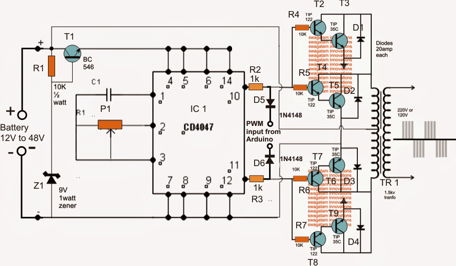
As per the request the first diagram below shows a single phase PWM sine wave inverter using an Arduino feed for the PWMs.

The design looks pretty simple, the 4047 IC is configured as a totem pole astable for generating the basic 50 Hz or 60 Hz frequency.

This frequency drives the two power BJ transistor stages alternately at the specified frequency rate.

The transistors could be replaced with IGBTs for getting better efficiency, but mosfets should be avoided as these may require special attention while designing the PCB, and additional buffer BJT stages to prevent heating up of the mosfets from possible hidden stray inductance or harmonics.
Circuit Operation

In the above diagram P1 and C1 determine the frequency of the astable which can be adjusted by suitably setting up P1 using a frequency meter for the intended inverter operating frequency.

T1 and the associated components which stabilize a fixed 9V for the IC 4047 may be eliminated if the selected inverter operating voltage is not over 15V, however higher voltage up to 60V could be tried and is recommended for achieving a compact and a more powerful inverter design.

The PWM from the Arduino is applied across voltage divider networks over the two outputs of the IC via reverse biased diodes which make sure that only the negative pulses of the PWMs interact with the power stages and chop their conduction appropriately.
As a result of these PWM chopping effect, the induced current inside the transformer is also correspondingly shaped for achieving the intended PWM sinewave stepped up mains voltage at the secondary of the transformer.

The PWM frequency from the Arduino must be set at around 200 Hz, if a programmed 50 Hz totem pole is available from the Arduino then the IC4047 can be entirely eliminated and the signals can be integrated directly with R2, R3 left side ends.
 

You'll also like:

  • 48VinvertercircuitSimple 48V Inverter Circuit
  • outputcontrolledinvertercircuitAutomatic Inverter Output Voltage Correction Circuit
  • lowtohighpowerinverterupgradecircuitHow to Convert a Low Power Inverter to a High Power Inverter
  • 5kva inverter circuit5kva Ferrite Core Inverter Circuit – Full Working Diagram with Calculation Details

Filed Under: Inverter Circuits Tagged With: Arduino, Interface, Inverter, PWM

About Swagatam

I am an electronics engineer and doing practical hands-on work from more than 15 years now. Building real circuits, testing them and also making PCB layouts by myself. I really love doing all these things like inventing something new, designing electronics and also helping other people like hobby guys who want to make their own cool circuits at home.

And that is the main reason why I started this website homemade-circuits.com, to share different types of circuit ideas..

If you are having any kind of doubt or question related to circuits then just write down your question in the comment box below, I am like always checking, so I guarantee I will reply you for sure!


Previous Post: « Simple Digital Stopwatch Circuit (4-Digit)
Next Post: Making a Strong RF Discharge Circuit »

Reader Interactions

Questions & Answers

Total Posts: 8
Newest Oldest
Amjad Ali
April 3, 2015 • 11 years ago #29706

without feedback and SPWM, sine wave and regulated output doesn't seem viable 🙁 very difficult without MCU or baba Oscillator with CD4047BC Monostable/Astable Multivibrator diffidently impossible.

Reply
Atton Risk
February 17, 2017 • 10 years ago #49040

This can kind of all be done using software such as SPWM on github

Reply
a rahman
June 10, 2020 • 6 years ago #79336

would you mind helping me by sending me the details and the whole circuit diagrams of pure sine wave inverter 12vdc to 220vac?
if you wouldn’t please send to my email

Reply
SwagatamAdmin
June 10, 2020 • 6 years ago #79339

you can try this:
Arduino Pure Sine Wave Inverter Circuit with Full Program Code

Reply
NGwabeDavid
March 26, 2026 • 6 months ago #203492

Hullo I request for a. Charger circuit that can charge Spiro battery

Reply
SwagatamAdmin
March 26, 2026 • 6 months ago #203510

Hi, please provide the complete specifications of your EV battery, then I will try to help!

Reply
Ngwabe david
August 5, 2026 • 2 months ago #211373

thack for the reply the batery is 72volts 3312wh 46ah modelWAH7447 Manufacturer xiamen

Reply
SwagatamAdmin
August 6, 2026 • 2 months ago #211457

You can try the following circuit. You will have to press the push button to initiate the charging process…the battery will cut off and latch full charge level and also at low battery level. Adjust the 10k preset for the low battery latch, and adjust the 470k/2.2k divider for the full charge cut off latch:
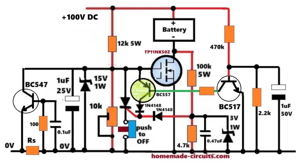
72V battery charger circuit

Reply

Need Help? Please Leave a Comment! We value your input—Kindly keep it relevant to the above topic! Cancel reply

Your email address will not be published. Required fields are marked *

Primary Sidebar

My YouTube Channel

Circuit Simulator: Draw and Simulate Schematics

circuit simulator image


Categories

  • Arduino Projects (95)
  • Audio and Amplifier Projects (134)
  • Automation Projects (18)
  • Automobile Electronics (104)
  • Battery Charger Circuits (90)
  • Datasheets and Components (109)
  • Electronics Theory (151)
  • Energy from Magnets and Earth (43)
  • Games and Sports Projects (11)
  • Grid and 3-Phase (20)
  • Health related Projects (27)
  • Home Electrical Circuits (13)
  • Indicator Circuits (16)
  • Inverter Circuits (98)
  • Lamps and Lights (161)
  • Meters and Testers (72)
  • Mini Projects (28)
  • Motor Controller (68)
  • Oscillator Circuits (30)
  • Pets and Pests (15)
  • Power Supply Circuits (91)
  • Remote Control Circuits (50)
  • Security and Alarm (65)
  • Sensors and Detectors (107)
  • SMPS and Converters (46)
  • Solar Controller Circuits (62)
  • Temperature Controllers (44)
  • Timer and Delay Relay (51)
  • Voltage Control and Protection (44)
  • Water Controller (37)
  • Wireless Circuits (31)


Subscribe to get New Circuits in your Email


Other Links

  • Privacy Policy
  • Cookie Policy
  • Disclaimer
  • Copyright
  • Videos
  • Sitemap

People also Search

555 Circuits | 741 Circuits | LM324 Circuits | LM338 Circuits | 4017 Circuits | Ultrasonic Projects | SMPS Projects | Christmas Projects | MOSFETs | Radio Circuits | Laser Circuits | PIR Projects |


Recent Comments

  • Swagatam on How to Connect IC 4066 in a Circuit
  • Swagatam on How to Check a MOSFET Using a Digital Multimeter
  • Darmco on How to Check a MOSFET Using a Digital Multimeter
  • Philemon Sakachiba on How to Connect IC 4066 in a Circuit
  • Swagatam on Adjustable Voltage Regulator Circuit using LM324 IC with Over Current Protection

Social Profiles

  • Twitter
  • YouTube
  • Instagram
  • Pinterest
  • My Facebook-Page
  • Stack Exchange
  • Linkedin

Calculators

  • ZVS Induction Heater + Tank Calculator Tool
  • Zener Diode Calculator
  • Wire Current and Thickness Calculator (Ampacity Calculator)
  • Voltage Divider Calculator
  • Transistor Base Resistor Calculator
  • Transistor Astable Multivibrator Calculator
  • TL431 Calculator
  • Solar Panel, Inverter, Battery Calculator
  • Ferrite Core Air Gap Calculator Tool
  • Parallel MOSFET Calculator Tool: How to Connect MOSFETs in Parallel Safely
  • LC Resonance Calculator for EV Battery Charger Circuits
  • LED String Series Resistor Calculator
  • PFC (Power Factor Correction) Calculator Tool: 3kW
  • Passive Power Factor Correction (PFC) Calculator
  • LM567 IC Calculator Tool
  • SMPS Flyback Boost Converter Calculator
  • Shunt Resistor Calculator for Ammeters
  • SCR and Triac Gate Resistor Calculator
  • Battery Back up Time Calculator
  • Boost Converter Calculator (Non-Isolated)
  • Bootstrap Capacitor Calculator
  • Buck Converter Calculator
  • Buck-Boost Converter Calculator
  • Capacitance Reactance Calculator
  • DCM Flyback Transformer & Wire Gauge Wire Size Calculator Tool
  • Filter Capacitor Calculator
  • IC 4047 Calculator (Frequency and PWM)
  • IC 4060 Calculator
  • IC 555 Astable Calculator
  • IC 555 Monostable Calculator
  • IC SG3525, SG3524 Calculator
  • Inductance Calculator
  • Induction Heater Inductor and Resonant Frequency Calculator
  • Induction Heater Work Coil Calculator
  • Inverter LC Filter Calculator
  • LC Resonance Calculator
  • LED Current Calculator
  • LM317, LM338, LM396 Calculator
  • NAND/NOT Gate RC Values Calculator
  • NOT, NAND Gate Frequency Calculator
  • Notch Filter Calculator Tool
  • Ohm’s Law Calculator
  • Phase Angle Phase Shift Calculator
  • Power Factor (PF) Calculator
  • RC Filter Calculator
  • Reactance Calculator
  • Sine Table Calculator for SPWM Arduino Code
  • Small Signal Transistor(BJT) and Diode Quick Datasheet
  • SMPS Calculator for Toroidal Ferrite Transformers
  • SMPS Flyback Transformer Calculator – Design by Target Duty Cycle
  • TL431 Calculator
  • Op-Amp Hysteresis Resistor Calculator

© 2026 · Swagatam Innovations