In the following article I have explained 3 useful DC to DC uninterruptible power supply circuits or DC UPS circuits for low DC to DC uninterruptible power applications
The first idea below presents a DC UPS circuit can be used for providing back up power to modems or routers during mains failures, so that the broadband/WiFi connection never gets interrupted. The idea was requested by Mr. Galive.
Technical Specifications
I need a circuit like,
I have two 12v dc adapter(600mA and 2A).
When input Mains is present, with the 600ma adapter i want to charge the battery(7.5AH) and with the 2A adapter i want to use my wifi router.
when the AC mains fails the battery will backup my wifi router without interruption.like UPS.
MY modem is rated as 12V 2.0A. That is why i want to use two 12v dc adapter.
The Design
Two adapters actually are not required for the proposed application. A single adapter, probably the one which is being used for charging the laptop battery may be used for charging the external battery also.
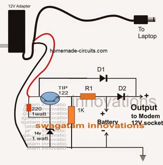
Looking at the given DC modem UPS circuit diagram we can see a simple yet interesting configuration involving a couple of diodes D1, D2, and resistor R1.
Normally a laptop charger is specified with 18V, so for charging a 12V battery this needs to be lowered to 14V. This is easily done using a transistor zener stage.
When mains is present, the voltage at D1 cathode is more positive than D2, which keeps D2 reverse biassed. This allows only D1 to conduct, supplying the voltage from the adapter to the modem.
D2 being switched OFF, the connected battery starts receiving the required charging voltage via R1 and begins getting charged in the process.
In an event AC mains fails, D1 gets switched OFF, and therefore allows D2 to conduct, enabling the battery voltage to instantly reach the modem without causing any interruptions to the network.
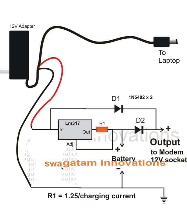
R1 must be selected depending upon the charging current rate of the attached battery.
A much better and improved version of the above is shown in the following diagram:
2) 6V to 220V Boost UPS Circuit
The second circuit explains a simple boost converter UPS circuit for supplying an uninterruptible power to satellite TV set top boxes so that the offline recording is never allowed to fail during power outages. The idea was requested by Mr. Aniruddha Mukherji.
Technical Specifications
I am an enthusiast electronic hobbyist person. Though I know only the basics, I am sure you must be getting 100's of emails daily and I am completely betting on my luck if this one gets to your "eyes"
My requirement:
16 volt 1 amp DC backup for my apartment Tata sky centralized distribution panel.
Issue: My apartment maintenance people do not run backup (generator) during day time, I have a Tata sky DVR which fails to record since there is signal loss due to power failure.
Resolution:
I had thought of a small back up system,I had purchased a small 6 volt 11 watt CFL Ballast circuit thinking as cheap alternate solution, but the same failed to work.
Why I am looking for AC supply instead of DC?I do not want to tamper with their system and get penalized for whatsoever failures which may come to it due to natural course of operation.
Could you please help me with a very simple cost effective circuit that will give me 220 volt 20 watts power from 6 volt 5ah battery. To be precise 220 volts from 6 volt battery, as I have purchased a 6 volt 5 ah battery recently. The output wattage requirement is less than 20 watts, the
adapter ratings are :
Output - 16 volt 1 amp
Input - 240 volt .06 amp
I know you have lot of work, but if you could spare some time and help me with this it would be of great help. thank you
Thanks,
Aniruddha
The Design
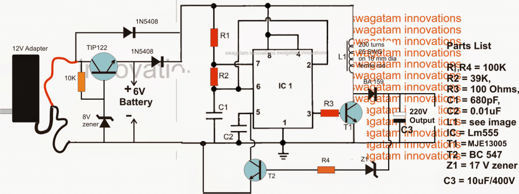
Since today all electronic systems employ an SMPS power supply, the input does not necessarily need to be an AC for powering these equipment, rather an equivalent DC or pulsed DC also become useful and works as good.
Referring to the diagram above, a couple of sections can be seen, the IC1 configuration enables a 6V DC to be boosted to a much higher 220V pulsed DC through a boost converter topology using the IC 555 in its astable form. The extreme left side battery section ensures an changeover from mains to battery back up every time a power failure is sensed by the circuit.
The idea is pretty simple and does not require much of an elaboration.
How the Circuit Functions
IC1 is configured as an astable oscillator, which drives T1 and consequently L1 at the same frequency.
T1 induces the entire battery current across L1, causing a proportionately boosted voltage to appear across it during the OFF periods of the T1 (induced back EMF from L1).
L1 must be appropriately calculated such that it generates the required magnitude of voltage across the shown terminals.
The indicated 200 turns is tentatively figured out and might need much tweaking for achieving the intended 220V from the input 6V battery source.
T2 is introduced for regulating the output voltage to the desired safe levels, which is 220V here.
Z1 should be therefore a 220V zener, which conducts only when this limit is exceeded, which forces T2 to conduct and ground pin5 of the IC, stalling the frequency at pin3 to a zero voltage.
The above process continuously readjusts itself rapidly ensuring a constant 220V at the output.
The adapter which can be seen at the extreme left is employed for two reasons, first to ensure that IC1 works continuously and produces the required 220V for the connected load regardless of the mains presence (just as we have in online UPS systems), and also to ensure a charging current for the battery when mains voltage is present.
The associated TIP122 transistor is positioned to generate a regulated 7V DC for the battery and also to restrict over charging of the battery .
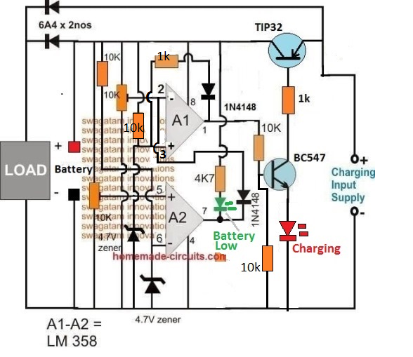
Using Op Amp Cut OFF
If you want a precise circuit which will accurately monitor the DC UPS battery and implement the required over charge and low discharge cut OFFs, the following design may prove useful.
3) Redundant DC UPS Circuit
In this third concept below I have explained a couple of straightforward redundant UPS circuits for providing a secured uninterruptible power to crucial gadgets such as computer ATX or modems etc. The idea was requested by Mr. Shayan Firoozi.
Circuit Objectives and Requirements
- There are many products which has 2 input for different power supply,for example one for normal mains,one for generator or other mains,like servers,routers,and some critical equipment,we call it redundant power supplies
- I have an equipment which consumes 3 ampere in 12 volt dc,if I use 2 transfer with 12 volt,3 amp output which one take responsibility and which one is waiting for first loss?? Both are same on voltage and amperage,I don,t want them to work together,
- I want second power supply to be standby
- Just a simple question: What would happens if I replace battery with another 12 volt power supply ?? Will it work as a redundant or standby power supply ??
- Thanks for your answer in advanced And if it's possible tell us about model of diode and other components for 12 volt 3 ampere
The Design
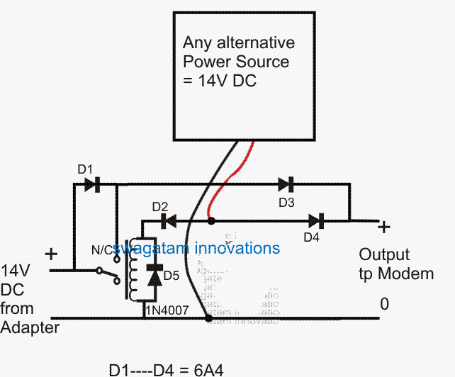
As per the request, the circuit discussed in the above link can be modified to work with another DC power supply by eliminating the battery and associated stages as shown in the following form of redundant UPS circuit:
Using Two Power Supply Inputs
As we can see, the circuit is intended to work with a couple of power supplies having identical specs, such that whenever the primary power supply fails, the relay instantly changes over to the secondary power supply source ensuring an uninterruptible power supply to the connected load.
The diode D1 makes sure that while the primary power source is active and the relay in the deactivated position, it connects in series with D3 creating a greater forward drop than the primary supply diode D4...thus allowing the primary voltage to be in command and powering the load.
However as soon as the primary source goes through an outage, D4 is disabled, and for that split second D1 and D4 takes over powering the load, until the relay has changed over bypassing D1 and enabling the full rated power to the load.
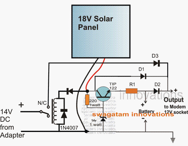
The next diagram shows a method which allows a battery to be included within the proposed redundant UPS circuit, and the primary power source replaced with a solar panel, making the system a 3 way protected UPS circuit
Using Power Supply with Battery
Referring to the diagram, as long as the solar energy is available, the relay stays activated keeping the mains derived 14v supply cut off from the system.
The solar power in the meantime charges the battery and also the connected load via D1.
The battery power being slightly subdued than the solar panel power keeps D2 deactivated such that only D1 is allowed to carry the solar energy to the attached load at the output.
Using TIP122 for CV Battery Charging
The TIP122 ensures a regulated and safe over charging protected supply for the battery which charges solely through the panel voltage during day time.
As night sets in, the relay deactivates at some of time when the solar supply gets too weak to hold the relay activated.
The above changeover instantly switches the mains operated 14V into the system enabling the load to switch to the mains derived voltage without an interruption.
The battery power makes sure that while the relay is transferring over from the solar to the mains adapter supply, it compensates the split second changeover lapse in power by supplying its own power to the load, and inhibiting even a microsecond break of supply for the load.
The battery also forms the third "line of defense" in case both the primary and the secondary power happens to fail together, and is always positioned in the standby mode for the recommended redundant uninterruptible power supply circuit operation.
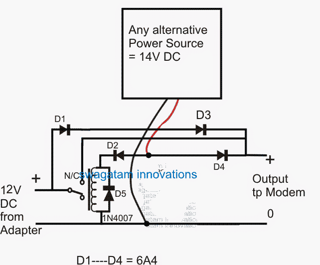
The first redundant UPS circuit incorporating two power sources can be better modified in the manner shown below, here the relay N/C can be seen directly connected with the load, thus enabling zero drop in the supply line:
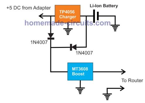
Modem UPS using TP4056 Li-IOn Charger
If you are interested to make a 5 V DC UPS for your router using high end chargers such as TP4056 and boost converter modules, the following design could help:
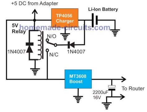
The above design could be also built without a relay as given below:


Questions & Answers
Tanks!, you can try the LAST circuit shown in the foowing article:
https://www.homemade-circuits.com/2012/07/making-simple-smart-automatic-battery.html
Ignore the LM338 stage and connect the 14V supply directly across the N/C of the relay and ground….the two diodes connected at the positive of the batt make sure that the batt is held at 13.5V everytime the relay trips at 14.5V.
I have no 1N5402. Would it be possible to use a 4004 instead in this application? Forward voltage drop is only 1.1V (1V for the 5402), and allows for less amperes. If used with a low-draw modem, would such a replacement be correct?
And if I want to power both a modem and a router from the same battery, different voltages, would I be able to use my DC booster to get the required 18V for the modem while keeping 12V for the router?
1N5402 will handle upto 3 amps while 1N4004 not above 1 amps.
yes you can use a booster circuit for getting the required 18V for the same source.
Thanks for your quick answer Swagatam. My goal is to re-use small 12V batteries I have to power the essentials: Modem and internet gear!
I will be using the inverter in a car. Considering the hassle associated with building a homemade inverter (namely, hard-to-find transformer and costly radiators), I'd rather buy a ready-made one.
Oh, and what wattage should R1 be? Charging current squared times number of ohms calculated?
I am a bit afraid that this DC UPS, having no charging regulation, reduces the battery life.
In the second circuit which uses the IC 317, wattage of R1 will be 1.25 x battery AH/10, yes without an auto cut-off it wouldn't be the best of the chargers, however the inclusion of the 317 current controller stage would help to keep the battery safeguarded to a considerable extent.
Hello,
I have a router of rating 9V, 0.6A. Can I use the same circuit with output voltage set to 9V. Plz suggest a battery rating for this configuration.
for a 9v router the output voltage must be set to 10V and a 9V/4ah battery could be used
Hi Swagatam,
This is a nice solution I have been looking for and very simple to implement, but I want to use it to power a monorail motherboard, that is rated for 12V, but a about 5A, what do I need to do to this circuit to help me deliver 12V, 6A, and what battery capacity do you recommend.
Thanks Elijah,
for a 12V 6A load the recommended battery would be a 12V 40 ah, this would provide a back up of around a couple of hours max.
For this you can simply eliminate the resistor R1 (in the second design) and use a LM338 IC in place of the IC 317.
LM338 is specified for operating at maximum 5amps, so the battery would be always charged at the optimal rate of 5amps safely.
HI Swagatam,
I appreciate your magnanimity at your replying me. I actually have implemented the circuit replacing Lm 317 with LM 338. It work quite well, but figured out that Diode D1, is getting very hot, I have to shut down. My guess was that the load (a monorail motherboard with other accessories are drawing a lot of current, while the battery is also charging. I changed the diode to 1N5408…thinking it should work, yet it is still very hot, though it worked well, I also eventually have to shut it down what do you advise, what am I doing wrong?
And or what am I suppose to do?
2- My adapter has a light by the side that lights up when its doing it job. I also discovered that despite taking the mains off, but battery is still connected to my board, the green light on the adapter still lights up/ Hope current is not flowing back from battery…..
Hi Elijah,
Is the diode getting hot even without the load connected? If so then there could be some problem with the LM338 circuit. Otherwise its fine, you may put a couple of more1N5408 diodes in parallel to the existing one.
To stop a reverse flow of current from the battery, put a diode at the input of the LM338, this will prevent the battery voltage from leaking back to the modem.
Hello Swagatam,
Thank you so very much on this, without Load, I have not experience the heat, but I will check again and observe. Do you have any recommended make of the 338.
I will try to work on the leakage and feed you back.
Am doing an additional follow up despite sending you an earlier one. The reverse current still flows, despite putting a diode, may be am putting it wrongly. Kindly help. This is the way I did it. Am using 1N5401 for this, this is the arrangement, the input positive power rail is connected to the anode of the diode and the cathode of the diode connects to the input of the LM 338…. Is that right?
Secondly, I have also added 2 additional diodes in parallel to D1.
Thanks for your support.
Elijah, that cannot be possible…a diode at the input of the LM338 will never allow an opposite flow of current,
the suggested diode connection is correct.
The band side of the diode is the cathode.
Swagatam,
everything works well, but am having problem with the diodes, I used 4 1N5401, but they are still getting warm…..what should I do with this diodes…..
…with load connected or always??. check the current consumption by an ammeter to confirm if everything's correct.
..with load connected only, in fact if i put a small load less than an 1amp, no problem, until i put the entire load on it, or should i go for a higher diode , like 6 or 10amps?
yes, in that case you can put more diodes in parallel or use a single 6/10amp diodes
…with load connected, with smaller load no issues….smaller load of about .5A. At full load, Ammeter shows an average draw of 3.5A, sometimes it oscillates between 3.4 to 3.8A. what surprises me is that the 338 never even warm up talk less of very hot, I thought it will heat up initially, so I mounted it on a heat sink. Surprises, it never warms up even, its cold there…
that's strange…at 3.5Amps the IC should get very warm….I am not sure if everything's correct in the circuit,
try different values for R1 and check the amp consumption, if it varies accordingly then you can assume it to be OK.
hello Swagatam
first of all i have to thank you very much for your nice work.
i have a 12v.5A router, wireless phone "panasonic" 6v/0.5A , an acid battery with 100 amp and a 20A charger for the battery…
1.i want this ups but without charging myu battery "because i have a chagrger"
2. could i put 7806 regulator on output to run my wireless phone ?
3. i have a 12v/1.25A and laptop charger 19v/3.5A.. which one should i use ??
and thank you again
Thank you Ahmad.
I did not quite understand how you are planning to use the above circuit.
Do you mean you want the 20A charger in place of the adapter shown in the above circuit??
2. yes 7806 can be used at the output
3. If you intend to use it as the input source, you can use a 14V adapter, if the battery is rated 12V, but none of this would be able to charge a 100AH battery.
i like to build this circuit but without charging feature because i want to charge the battery manually
i mean.. i will use an adapter 12v as main current but i dont want it to charge the battery… i want it only to be the main current…
when the adapter power fail… the battery will give the current instead of the adapter…
when i notice that the battery need to be charged.. i will connect my 20amp charger manually..
hope u get my idea
thank you again
Ok, the following design will be sufficient in that caes:
1.bp.blogspot.com/-I2zlapFq6RM/UML_NxUJy2I/AAAAAAAAB3w/27ZLDjK9C9g/s1600/simple+modem+UPS+circuit.png
The entire R1 link may be included excluded, it won't make much of a difference.
use 1N5402 for the diodes.
thank you very much for your advice
i did what you told me… but i got a problem
since i use a 12v adapter..when i connect it with diode it decrease to 11.5v and since i use a car battery.. most of time it gives 13.5-12.5v so its always above the adapter.. so its always take the lead.. and the adapter only work when i disconnect the battery.. (the circuits do the opposite of its purpose" 🙁
so should i put some 7812 for the battery?? or use a higher volt adapter like 14v?? but am afraid for the router because its 12v only
thank u again
yes, a 7812 with the battery output would solve the problem instantly.
If possible use an adapter which has a feature of fine-tuning the output through a preset.
This would allow you to increase the adapter voltage slightly, may be to 13V for getting a perfect response.
Hello Swagatam,
just made this circuit with a 1ohm resistor to provide a lower (thus safer) current to my 4.5Ah battery. I used it with a 12V adapter, but forgot that a 12V battery needs about 13V to charge properly, whereas there's only 10.5V on battery terminals. Is the circuit built with 9V batteries in mind by any chance?
Hello Pat, the adapter voltage should be 14V, the diagram shows a standard value adapter (12V) which could be ignored and a 14V must be used.
my router is 12v(0.8A)
battery=12v 3.5AH
give some suggestion about using this circuit?
thanks
you can use the above circuit with a 14V adapter, but 3.5ah won't last too long during back up.
Most laptop adapter nowadays output 18.5 to 19V. I guess they're OK for laptop use, of course, and would give the required 13.8V to the battery?
OK, that's fine Pat!
sir, i want to eliminate the charging system.
I just want to connect the wifi router with battery when the AC(Main) fails.
I have use a relay for desired operation but when the AC(main) fails the device restarts and wifi connections are disconnected.
use only D1, D2 for it.
D1 comes from the adapter positive, D2 from the battery positive, their common cathodes ends join with the router positive.
at this configuration when the ac main is present the battery is not consuming or it is consuming??
In this configuration the battery would have no connection with the adapter voltage and would not get charged.
sir i want to construct a 14v and 10A transformer but i do not know about wire diameter, number of turns and aria of bobbin. so kindly guide me or send me any link that is helpful to beginners.
Shahab, I too do not have much knowledge regarding designing of transformers, so I won't be able to provide any help
ok sir, that is good. thanks
hi Swagatam,
i have a laptop charger "19v, 4.2amp" i build a voltage regulator lm338 to use it as a 12v battery charger..with variant resistor.. and i adjust it to get 14.5v to charge the battery.. but the output current had never crossed 1.7 amp.. even if the battery is fully discharged.. why?? you told me that lm338 output could reach 5amp.. so what is the problem?? why cant i get at least 4 amp??
another question.. when the battery is fully charged.. the output current from charger is near 0.2amp.. does that mean the charging is stopped?? or this current will harm my lead acid battery??
and thank you very much
Hi Ahmed,
Either the input charger is not supplying 4 amps to the IC LM338 or the IC LM338 is faulty or duplicate….a good IC and a good charger will definitely allow full 5amp to the load….of course only if the load would be consuming this much current.
By the way what is the AH rating of the battery??
When the battery is fully charged it will naturally stop accepting current from the charger but that doesn't mean it's not being charged, the input will need to be switched off in order to avoid damage to the battery in this situation.
what do you mean by AH rating??
and about the charger .. i tried to apply the charger directly on battery "with 19v" it gives 4.2amp.. but when i use the regulator it's never cross 1.7
thanx again
AH means ampere/hour it can be seen printed on your battery body
if you apply 19V to a 12V the battery it will get damaged quickly, so it's never recommended even for a short duration.
Your ICLM338 is faulty for sure, a good IC will allow the full amp to be delivered to the battery depending on how the battery is pulling….
test the battery charging amp with a different 14V source that will give a clearer idea regarding the consumption.
it's 70AH .. and when i charge using another charger it get 10amp.. but thats mean like you said that the ic is very bad..
anyway thank you very much
for a 70AH battery LM338 will not work anyway, because the batt will need around 8 to 10amp charging current and LM338 can provide max 5amp, better to use a 14V 10amp smps and charge the battery with it directly for 8 hours.
Hi Swagatam,
I want to use an external 3.6VDC 700mAh Lithium Battery as backup instead of charging it from main supply & want to drive a 5W light rather than modem/router will this work?
Hi Dipto, do you mean you don't want the LM317 or the TIP122 stage and want to use only the diodes for the changeover?
Yes the above circuit can be used for your application too….but a 5 watt light will be too big for the mentioned battery, will drain it quickly
Hi Swagatam,
Can I use 3ah battery instead of the 7.5ah one? The suggested 14v adapter is not widely available on our market? If 12v one is used, will it not work? And if 15v adapter is used, will the router run a risk of burning out?
Hi Roney, yes 12V 3ah can be used but it will give a proportionately lower backup time compared to a 7ah battery
you can easily make a 14V power supply by using a 0-12V/1amp transformer and then rectify its output with a bridge network and capacitor
Thanks a lot. I'm just a new comer to electronics. May I ask for any link of that bridge network design to get 14v from 12v transformer? And what would be the R1 value in case 3ah 12v battery?
Please refer to the third circuit from this article, a basic transformer bridge capacitor circuit is shown, please connect them exactly as shown for implementing the required cirucit:
https://www.homemade-circuits.com/2012/03/how-to-design-power-supply-simplest-to.html
hi sir…..appreciate your work
actually i have a 12v and 30amps(not sure) and i wanna use it to power my 12v 1amp modem ….what changes should i made for that in this schematic that exactly fulfil my requirements and do not damage my modem ,…..i am waiting for your kind suggestions
thanks mudassir,
you can use the same circuit for a 12V 30amp battery also, no changes would be required except the following
in the second circuit, use LM338 instead of LM317 and use 0.25 ohms/1watt for R1
in the first circuit remove R1 and replace it with a wire link.
thanks….and what if i plan to use it permanently with modem .i mean if the battery is over charged will this circuit stop charging ?
the first circuit will stop overcharging of the battery, the second circuit will not do this.
Can you please modify and incorporate the second circuit to prevent overcharging plz?
dear sir , i followed all your instructions for the above mentioned circuit but unfortunately i could not found the Lm338 and 1N5402 instead there is 1N4007 available here.so i want to know if there is any way of connecting my modem directly to the battery and is it possible to use a 1A fuse in line …..2ndly can i charge my 12v 30Ah battery with 12v 1A charger which is at the same time powering the modem also???? any help will be appreciated pls help…. i'll be waiting for your ans from now
I am sorry mudassir, the diodes are the heart of the circuit, with no diodes the circuit would become meaningless, so you must find 1N5402 or iN5408 diodes for you particular application. 1N4007 will not do
12v/1amp will not charge a 12V/30ah battery properly…the adapter should be rated at 14V/3amp minimum.
many thanks sir …..i'll try once more
hello Swagatam majumdar ….i found an adopter and there is 5-13v 700mA stated on it will it charge 12v 30Ah battery ….if yes then it will take too long to charge fully what you say?
hello mudassir…13v will just not work…it should be at least 14.5V…and at 700mA it may take ages to get your 30ah battery fully charged.
yahooo…. i did it easily with a simple way… i connect a 1A fuse inline and connet it with 12v 30Ah battery directly and it worked fine for me now i can use it for 25-28 hours continously powering my dsl without any problem i used a 2way switch between battery and 12v dc adaptor …..
sir i have made this circuit but i am not sure whether the battery is charging or not because i have also used an ammeter in series with battery junction and its shows no current flowing into the battery while mains is available
Zainey, what is your battery Ah rating? and what is your input current range and what resistor have you used in series with the battery?…what is the FSD range of the ammeter that you have used?…specify all these I'll try to troubleshoot it.
Can a relay be used for auto backup function in this circuit if so then plz tell and give the circuit diagram for that
relay is not required here, the diodes do the changeover automatically….for relay operation the diode set up won't be required, it may be done simply by using a single relay with the mains adapter supply and wire its N/O, N/C contacts with the load and the battery
hello sir i want to make wifi ups for 5v 1a and mean to say that when the ac power is on the router is on the ac power and that time the battery will also on charging and when the ac power is off or cut router is on on the battery power when the ac is on the router will run on the ac power sorry for bad english and i hope you will help me plzz
Hello Syed, the above indicated circuits are exactly as per your application needs, you can try any one of these for implementing the same.
can you plz tell me the names of the item which you used in this circuit
thanks again i hope you help me again
D1, D2 are the diodes, TIP122 is the transistor, LM317 is an IC, the 14V/1watt part is the zener diode
hello can we use the diode name 1N4007 as on 1N5402
no, 1N4007 will burn at 1amp..you can use either 1N5402, 1N5408 or 6A4 diodes
But i check my router with multimeter router is droping the ampere about 0.40 at full load
sorry I could not get your point…please elaborate what exactly are you referring to?
sir i have a battery 6v 4.5ah/20hr and i want to charge plz help me what voltage i use to charge the 6v battery
and i have a 12v charger can i use 12v charger to charge the 6v battery plzz help me plzz
Syed, you must use 7V as the input for the battery at the rate of 500mA current for your battery.
No, you should not use 12V for charging a 6V battery, it might damage the battery permanently or start internal gasing of the cells
ok bro can i use 8v i have a 8v charger at the rate of 700mA can i use plz help me..
ye, 8V/700mA will do, you can use it, if possible put a 1N4007 diode in series with the positive of the charger… this will drop the voltage to 7.4V…
Hello Brother, I have a 12v 7ah battery. And I want to use it for backing up a 12v 0.5Amp modem. I want to run this setup continuously. Thus iam worried about overcharging of the battery. which circuit is preferable in this situation. 1st pic or 2nd pic ? and I also have a 24v wall adaptor could I use it on this setup ?
Hello black bird, you can use the first circuit for charging your battery continuously without worrying, just make sure the zener diode is not rated above 14V. R1 can be selected arbitrarily, may be a 1 ohm resistor will be just enough…24V adapter can be used with the first circuit
Thanks For the Reply 🙂 . Any way Could you please list the exact values of items that are included in the circuit. And is these items are easily available ? especially the Transistor TIP122 and 14v Zener ? Thanks again 🙂
D1, and D2 cab be 1N5408 diodes, rest everything is given in the diagram itself, yes all these are standard components and should be easily available in the market.
Sorry Brother One More Doubt 🙂 , The adapter that is with me now is rated 24v 0.5A . So could it provide sufficient current to charge a 12v 7Ah battery ? Iam a newbie in electronics . So please help me ?
yes bro, it will be able to charge your battery, you can remove R1 for ensuring quicker charging, withing 8 to 10 hours.
Sorry to disturb You again , Iam getting 24v in between Modem out terminals , when using a 24 v power supply. and about 16v in between battery out terminals ? My modem is rated about 12v .? what to do ?
I am sorry blackbird, I just overlooked the fact that the 24V would get directly connected with your modem….please do the following change in the design…just disconnect the anode of D1 and connect it directly with the emitter of the TIP122….and entirely sure that the zener diode is rated at 14V or slightly lower, you can try connecting a 1K preset parallel with the zener diode for correcting the output voltage to the required precise levels
realy appreciate bro thanks buddy…… nice
you are welcome buddy!
What components shuld I use for a 5v 500mamp current…???
components can be the same, just use a 7V adapter and set R1 according to the formula.
hello Swagatam, I have Lead Acid battery with 6v 6Ah, laptop charger with 20V, 3.25mA. i want to use these thing to operate modem which operates on 12V, 800mA. Please help me to find the solution of this problem.
hello Athar, for operating a 12V modem with a 6v you'll require a boost converter circuit which could be quite difficult if you are a newcomer in the field of electronics.
HI Swagatam nice explanaations and ideas, i need help on similar need, here are what i have at hand
1.12 V 35 Amps exide battery
2.7V/7AH Batery
312 SMPS charger i am using to charge the exide battery
4.12V/1 Amp Adapter for modem
5.Modem
I wanted to have two circuits
1.To use with Exide battery -UPS circuit ,Charging with existing SMPS charger, and powering the Modem on power fail switch to battery power
2.To use with12V/7AH batter-UPS circuit charging the 12v 7Ah and powering the Modem on power fail switch to battery power
i did a stupid thing connecting 12 V 35 amps Exide battery directly to modem thinking that it just 12V and my modem is in't working now, i just bought new modem and seek your help. Yes i can assemble circuits on experimental boards
Kindly need your help, regards
Hi Chris, Thanks for posting your question!
The circuits explained in the above article are perfectly suited for fulfilling your requirements.
You can try the second circuit which is more sophisticated than the first one for both the needs..
A 12V adapter might not charge a 12V battery…the adapter output needs to be at least 14V to implement this.
If your modem is rated to operate at 12V, then I think you have done nothing stupid by connecting it to the 12V/35AH battery. Here the current is not important as long as the voltages are compatible…so it's quite OK to operate your 12V modem with any DC 12V source, even if it may be rated 1000 amp or 100000 amps
Thanks for the reply, with the same idea that it 12 V battery I connected, does polarity make any difference in DC connections probably I did not take care of polarity.
In that case, can i connect as following-> 12V SMPS charger to Battery terminals and From battery terminals to Modem Just like an on line UPS? do I have to incorporate any safety components from Terminals to Modem?
( they may calling it 12 V SMPS, but probably it is more than 12V it is actually used in UPS/Inverters for charging it is perfectly charging the exide battery)
yes, maintaining a correct polarity is definitely critical, a wrong polarity can instantly damage a particular device unless it may be protected with a diode.
It's possible to connect the units the way you have suggested and no safety measures are essential except for a battery over charge cut off circuit…or if you want to avoid this you can use a13.5V input instead of a 14.3V, which will never allow the battery to get 100% charged and therefore can be used without the over charger protection feature.
it would be advisable to measure the SMPS output volatge and make sure it's delivering above 13.5V
SMPS when not connected 13.70 When SMPS charging it is showing 13.35 , battery voltage is 12.80 when SMPS not connected ,Should we have any protection before the modem to limit it to 12 Volts/ I mean, is it necessary? if so what should we put there .
You can use two more diodes in series, meaning put two more diodes in series with D1, this will rectify the issue and drop around 1.2V from the adapter output for the modem
Hi sir
Just a simple question:
What would happens if I replace battery with another 12 volt power supply ??
Will it work as a redundant or standby power supply ??
Thanks for your answer in advanced