• Skip to main content
  • Skip to primary sidebar

Homemade Circuit Projects

Need circuit help? Post them in the comments! I've answered over 50,000!

Blog | Categories | About | Hire Me | Contact | Calculators-online
You are here: Home / Security and Alarm / Shock Vibration Detector Circuit using 801S Sensor

Shock Vibration Detector Circuit using 801S Sensor

Last Updated on July 17, 2023 by Swagatam 3 Comments

The shock alarm module that we are presenting to you can be used in a house as well as in a car. Given its low manufacturing cost, it can be replicated in several copies and connected to different positions at home. It can be also installed in a vehicle where it will trigger a siren when a strong vibration is detected. By: Ramdas

Table of Contents
  • Main Features of 801S Shock Detector (Learn More)
  • Electrical Characteristics of 801S Shock/Vibration Sensor
  • Circuit Description
    • Construction
  • How to Test

Main Features of 801S Shock Detector (Learn More)

The shock and position detector, for a more than affordable price, has very interesting characteristics that make it particularly suitable for alarm systems. It only requires a few very common and low-cost components for its implementation.
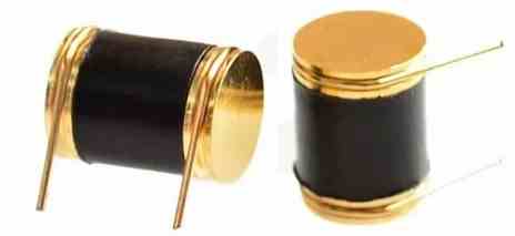
The photograph above gives an idea of its physical appearance. Its main features are as follows:

  • detection of very low amplitude shocks,
  • detection of changes in position,
  • detection in all directions,
  • guaranteed lifespan of at least 60,000,000 detections,
  • adjustable detection sensitivity,
  • operates without mercury (environmentally friendly!),
  • very high sensitivity,
  • completely static,
  • can be used for alarm, security systems, etc.,
  • dimensions: 0.7mm for a length of 9.2mm,
  • outputs on 0.5mm pins for printed circuit.

Electrical Characteristics of 801S Shock/Vibration Sensor

The electrical characteristics of the shock sensor 801S are:

  • Operating Voltage: 3.3V to 5V DC
  • Operating Current: <1mA
  • Output Signal: Digital (High or Low)
  • Sensitivity: Adjustable
  • Detection Angle: 360°
  • Detection Range: Up to 3 meters
  • Response Time: <15ms
  • Operating Temperature: -10°C to 70°C
  • Lifespan: 60 million detections
  • Dimensions: 9.2mm x 7mm

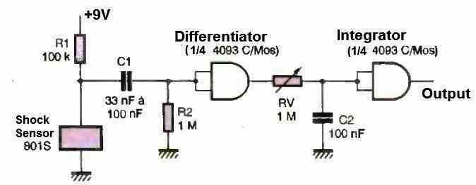
The basic diagram shown in figure above indicates what can be done simply with this 801S shock detector. Note that the output, when the 801S sock detector is triggered, provides a rectangular and unstable signal. The sensitivity is adjustable.

Circuit Description
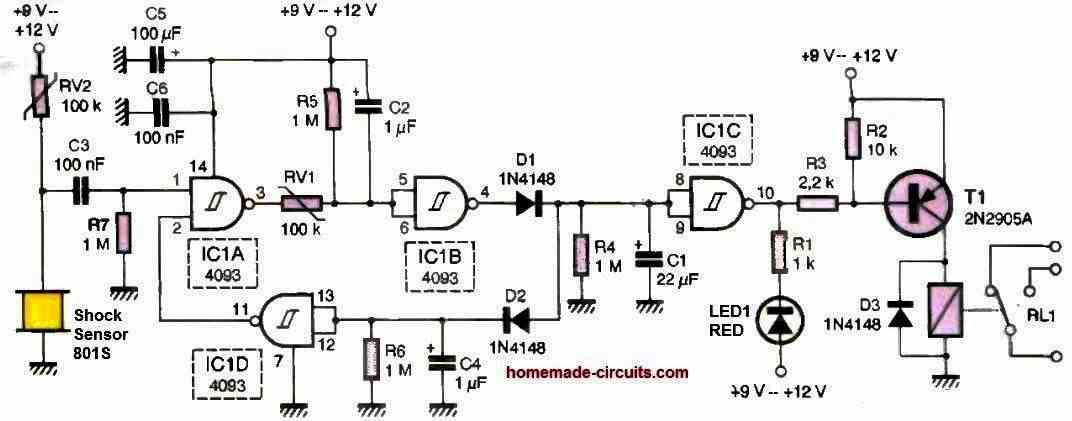
As can be seen in the figure above, shock detector circuit using 801S requires only a few components, in greater numbers than the first diagram, but giving better results.

The adjustable resistor RV2, which also adjusts the sensitivity of the circuit, constitutes a voltage divider with the 801S detector. When the sensor is triggered, the voltage at the input of the NAND gate IC1 (4093) changes and triggers the system.

A negative pulse appears on the output of this gate, which becomes positive at the output of the IC1B gate.

This pulse charges capacitor C1, and, inverted by the IC2C gate, makes transistor T1 conductive, which triggers the electromechanical relay.

On the other hand, it generates a negative pulse at the output of the IC1D gate, which will keep the IC1A gate low until capacitor C1 is discharged.

The relay will be activated for a few seconds, a duration that can be increased by changing the value of capacitor C1. The circuit can be powered by a voltage that can exceed 12V, which is the case in a car and almost all domestic alarm systems.

Construction

The printed circuit board layout and the component placement diagram of this 801S shock sensor is shown in the Figure below.
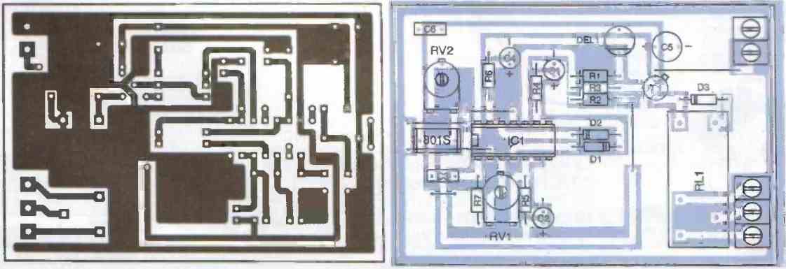
Six straps need to be placed on the board. As usual, start by placing the smallest components and end with the largest ones.

The power input and the three relay outputs (common, normally open, and normally closed) are made respectively on two- and three-point screw terminals.

The 4093 (IC1) will be placed on a socket, which will facilitate its replacement in case of an incident. If the circuit is independent, the power can be supplied by a 9V battery incorporated in the enclosure (in the case of a home alarm system).

After finishing the wiring, check the solder joints and the continuity of the tracks. If the board is used as a car alarm, apply a coat of varnish on the copper side to protect it from moisture.

How to Test

Regarding testing, there is nothing special to mention. Simply power up the board with the adjustable resistors set at mid-position.

By lightly tapping the board, the relay should activate.

Then adjust the potentiometers to achieve the desired sensitivity. For a value of 22 uF (C1), the relay stays activated for about six seconds. Its value can be increased if necessary.

You'll also like:

  • Microwave Sensor or a Doppler Sensor Circuit
  • How to Build a Rain Sensor Circuit
  • metaldetectorcircuit9 Simple Metal Detector Circuits Explained
  • motorcyclesecuritytransmittercircuitInfrared Remote Control Safe Lock Circuit

Filed Under: Security and Alarm, Sensors and Detectors Tagged With: 801S, Detector, Sensor, Shock, Vibration

About Swagatam

I am an electronics engineer and doing practical hands-on work from more than 15 years now. Building real circuits, testing them and also making PCB layouts by myself. I really love doing all these things like inventing something new, designing electronics and also helping other people like hobby guys who want to make their own cool circuits at home.

And that is the main reason why I started this website homemade-circuits.com, to share different types of circuit ideas..

If you are having any kind of doubt or question related to circuits then just write down your question in the comment box below, I am like always checking, so I guarantee I will reply you for sure!

Previous Post: « Mains AC Current Detector Switch Circuit
Next Post: 75 Watt Power Amplifier Circuit »

Reader Interactions

Questions & Answers

Total Posts: 3
Newest Oldest
Geo
May 31, 2023 • 3 years ago #143016

Very nice many thx for sharing

Reply
Eldo
March 25, 2025 • 2 years ago #170415

Hi very nice circuirt, nice solution. Can you tell me please whether your simple solution is good enough for a lot and frequent registration of vibrations? Actually I’m seeking for the solution for the gas cannon. You probable know that there is about 20,000 hits by only one LPG 12kg bottle. Can I be sure that this shock sensor can handle such a many vibrations?

Reply
SwagatamAdmin
March 25, 2025 • 2 years ago #170425

Hi, thanks for your feedback.
Yes, the above circuit looks accurate but I don’t think it can handle such intense vibrations.
Instead I would recommend using a piezo based sensor, as explained in the following article:
https://www.homemade-circuits.com/how-to-make-vibration-detectormeter/
Let me know your opinion on this.

Reply

Need Help? Please Leave a Comment! We value your input—Kindly keep it relevant to the above topic! Cancel reply

Your email address will not be published. Required fields are marked *

Primary Sidebar

My YouTube Channel

Circuit Simulator: Draw and Simulate Schematics

circuit simulator image

Categories

  • Arduino Projects (95)
  • Audio and Amplifier Projects (134)
  • Automation Projects (18)
  • Automobile Electronics (104)
  • Battery Charger Circuits (90)
  • Datasheets and Components (109)
  • Electronics Theory (151)
  • Energy from Magnets and Earth (43)
  • Games and Sports Projects (11)
  • Grid and 3-Phase (20)
  • Health related Projects (27)
  • Home Electrical Circuits (13)
  • Indicator Circuits (16)
  • Inverter Circuits (98)
  • Lamps and Lights (161)
  • Meters and Testers (72)
  • Mini Projects (28)
  • Motor Controller (68)
  • Oscillator Circuits (30)
  • Pets and Pests (15)
  • Power Supply Circuits (91)
  • Remote Control Circuits (50)
  • Security and Alarm (65)
  • Sensors and Detectors (107)
  • SMPS and Converters (46)
  • Solar Controller Circuits (62)
  • Temperature Controllers (44)
  • Timer and Delay Relay (51)
  • Voltage Control and Protection (44)
  • Water Controller (37)
  • Wireless Circuits (31)

Subscribe to get New Circuits in your Email

Other Links

  • Privacy Policy
  • Cookie Policy
  • Disclaimer
  • Copyright
  • Videos
  • Sitemap

People also Search

555 Circuits | 741 Circuits | LM324 Circuits | LM338 Circuits | 4017 Circuits | Ultrasonic Projects | SMPS Projects | Christmas Projects | MOSFETs | Radio Circuits | Laser Circuits | PIR Projects |

Recent Comments

  • Michael on Electronic Circuit Projects, Tutorials, and Practical Engineering Solutions
  • Swagatam on 24V to 12V DC Converter Circuit [using Switching Regulator]
  • Swagatam on Automatic Battery Full Cut-Off Latching Circuit with Trickle Charging
  • Ramin on Automatic Battery Full Cut-Off Latching Circuit with Trickle Charging
  • Joss on 24V to 12V DC Converter Circuit [using Switching Regulator]

Social Profiles

  • Twitter
  • YouTube
  • Instagram
  • Pinterest
  • My Facebook-Page
  • Stack Exchange
  • Linkedin

Calculators

  • ZVS Induction Heater + Tank Calculator Tool
  • Zener Diode Calculator
  • Wire Current and Thickness Calculator (Ampacity Calculator)
  • Voltage Divider Calculator
  • Transistor Base Resistor Calculator
  • Transistor Astable Multivibrator Calculator
  • TL431 Calculator
  • Solar Panel, Inverter, Battery Calculator
  • Ferrite Core Air Gap Calculator Tool
  • Parallel MOSFET Calculator Tool: How to Connect MOSFETs in Parallel Safely
  • LC Resonance Calculator for EV Battery Charger Circuits
  • LED String Series Resistor Calculator
  • PFC (Power Factor Correction) Calculator Tool: 3kW
  • Passive Power Factor Correction (PFC) Calculator
  • LM567 IC Calculator Tool
  • SMPS Flyback Boost Converter Calculator
  • Shunt Resistor Calculator for Ammeters
  • SCR and Triac Gate Resistor Calculator
  • Battery Back up Time Calculator
  • Boost Converter Calculator (Non-Isolated)
  • Bootstrap Capacitor Calculator
  • Buck Converter Calculator
  • Buck-Boost Converter Calculator
  • Capacitance Reactance Calculator
  • DCM Flyback Transformer & Wire Gauge Wire Size Calculator Tool
  • Filter Capacitor Calculator
  • IC 4047 Calculator (Frequency and PWM)
  • IC 4060 Calculator
  • IC 555 Astable Calculator
  • IC 555 Monostable Calculator
  • IC SG3525, SG3524 Calculator
  • Inductance Calculator
  • Induction Heater Inductor and Resonant Frequency Calculator
  • Induction Heater Work Coil Calculator
  • Inverter LC Filter Calculator
  • LC Resonance Calculator
  • LED Current Calculator
  • LM317, LM338, LM396 Calculator
  • NAND/NOT Gate RC Values Calculator
  • NOT, NAND Gate Frequency Calculator
  • Notch Filter Calculator Tool
  • Ohm’s Law Calculator
  • Phase Angle Phase Shift Calculator
  • Power Factor (PF) Calculator
  • RC Filter Calculator
  • Reactance Calculator
  • Sine Table Calculator for SPWM Arduino Code
  • Small Signal Transistor(BJT) and Diode Quick Datasheet
  • SMPS Calculator for Toroidal Ferrite Transformers
  • SMPS Flyback Transformer Calculator – Design by Target Duty Cycle
  • TL431 Calculator
  • Op-Amp Hysteresis Resistor Calculator

© 2026 · Swagatam Innovations