In this article I have explained a couple of simple vibration meter circuits which can detect and measure the strength of mechanical vibrations.
Video Clip demonstrating the Vibration meter working
The proposed circuits are built using transistors and also with an IC for getting a bar graph LED sequence for the level indications.
The bar graph LED could be calibrated and used for detecting and measuring the intensity of the vibration.
Introduction
Whether it's truck throttling over the highway, or an airplane roaring about the sky, or whether it's a knock on the door or a purring of the cat or simply your heartbeats, the vibration level detector circuit explained here will sense them all and convert into beautiful sequencing LED light bar graph indications.
The number of LEDs lit in the bar graph at any particular instant indicates the magnitude of the vibration force at that particular instant.
What is Vibration
Vibration is a form disturbance created over a medium such as air or a solid object, caused by an external interfering source.
For example when we speak, our vocal chords vibrate and generate the corresponding patterns of disturbance in the surrounding air.
When these air vibrations enter our ear, our eardrum also vibrate at the same frequency making it audible to our respective sensory organs.
Stronger vibrations make stronger impact on our senses and therefore we hear them louder in comparison to other sound levels.
The pitch of a vibration also becomes a major factor in determining their nature and strength.
Pitch and frequency are probably the two factors which make a particular vibrating information more distinct with their technical specs.
As an example, a whistling sound may be shrill and might reach longer distances, but the grumbling sound from a mixer grinder even being much stronger won't reach across longer distances.
Though our ear is equipped with pretty impressive detecting capabilities, these organs cannot tell you the exact magnitude of a particular vibration force.
Using Transistors Only
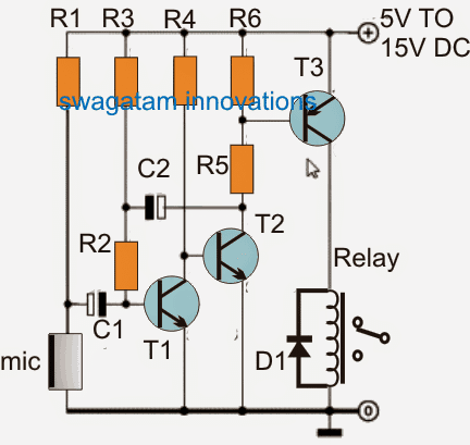
The diagram shown above works very efficiently as a simple transistorized vibration sensor. It will sense even the slightest sound from the surrounding or the surface over which it is installed.
C2 allows a delay period for the relay so that the relay remains triggered ON for sometime on each detection. The value of C2 could be tweaked for getting the desired delay OFF on the relay operation.
The relay could be attached with an alarm system if the circuit is intended to be used like a vibration operated alarm or a door alarm etc.
Parts List
- R1 = 4k7
- R2 = 33k
- R3 = 2M2
- R4 = 22K
- R5 = 470 OHMS
- R6 = 4k7
- C1 = 0.1uF
- C2 = 4.7uF/25V
- T1, T2 = BC547
- T3 = BC557
- D1 = 1N4007
- Relay = coil voltage as per the supply voltage, and contact rating as per the load specs
- Mic = electret condenser MIC.
Vibration Detector Circuit Working with LM3915
Another cool design can be built using IC LM3915 for detecting the strength of a particular vibration that might be emitted from some relevant source.
The circuit is basically a fun project, that may be built by a school kid and displayed in the school science fair exhibition.
The circuit diagram below shows a rather simple configuration using the versatile IC LM3915 from TEXAS INSTRUMENTS, which alone performs the function of sensing as well as displaying the vibration levels.
Pin #5 of the IC is the input which detects the variations in the induced sound via a electret microphone element.
A piezo transducer can be also tried instead of a mic. A piezo transducer element is a simple device used in piezo buzzers for emitting a sharp sound when connected to a frequency generator circuit.
However its being used for an opposite response here, that is for detecting a frequency rather than emitting it.
Sound vibration noise striking the MIC generate tiny electrical pulses inside the device, or rather the device converts all vibrations hitting its surface into small electrical signals varying in amplitude which corresponds to the strength of the striking vibrations.
These tiny electrical pulses from the MIC is effectively amplified and processed inside the IC LM3915 and the relevant sequencing LED display is generated across the outputs of the IC.
The LEDs connected at the outputs illuminate in randomly running patterns from the start point to the end point of the array, displaying the relevant information about the captured vibration signals.
This vibration detector or meter circuit can be further modified for more serious applications by including an alarm stage or a relay driver stage for triggering them in case a threatening level of vibrating force is detected.
The application may be user specified and therefore the present circuit might be configured or optimized in numerous different ways.
The IC needs negligible current and therefore a 9V PP3 battery would provide sufficient life to sustain the circuit, almost forever and also this makes the unit very portable and can be installed at any desired crevice or location.
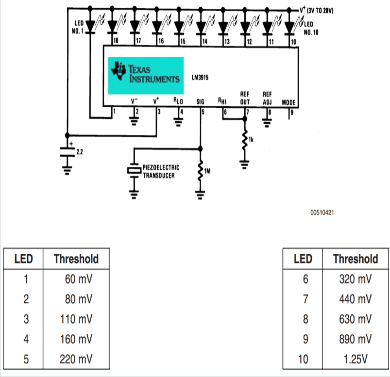
Although the above proposed vibration meter/detector circuit was taken from the original datasheet, it has many flaws and won't produce satisfying results until some serious mods are done.
Recently when I tested it myself realized the drawbacks it possessed. The tested and modified diagram can be seen below:
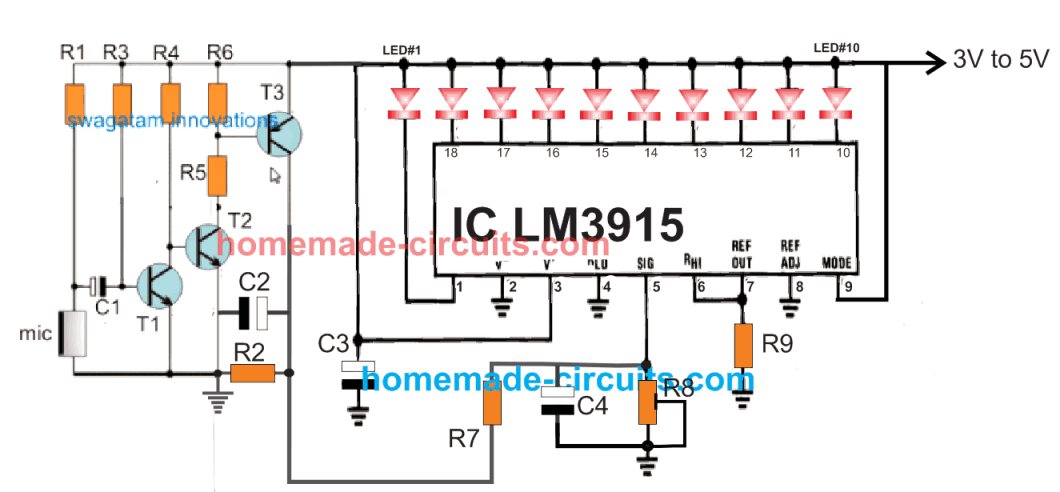
Parts List
- R1 = 5k6
- R2, R9 = 1K
- R3 = 3M3
- R4 = 33K
- R5 = 330 OHMS
- R6 = 2K2
- R7 = 10K
- R8 = 10K preset
- C1 = 0.1uF
- C2 = 100uF/25V
- C3, C4 = 1uF/25V
- T1, T2 = BC547
- T3 = BC557
- LEDs = RED 5mm type 20mA
- Mic = electret condenser MIC.


Questions & Answers
Hello,
I want to make a belt tension meter using acoustic system can i convert this vibration into frequency?
or can you help me with the names of sensors to use for this project
Your help will mean a lot to me
Hello,
a vibration by itself will have a frequency, and this will be amplified at the collector of T3…so yes you can use the first circuit to convert vibration into frequency. Make sure to remove the relay and the capacitor C2..also for better sharpness, you can add a couple of 1N4148 diodes in series with the emitter of T3
Thank you for you response it really means a lot and I had one more question can you tell me how reliable this system will be? Or should I go for some other ways toh calculate the belt tension?
Thanks, It’s my pleasure! The circuit will replicate the input vibrations into frequency quite reliably. You can connect a frequency meter across the collector of T3 and ground to get the results. However, the belt tension concept being new to me, I am not sure how the results can be interpreted and used for the required optimization of the belt tension.
Sorry for the late reply, and Thank you for your response.
Regards,
Shruti
You are welcome!
good morning me the same circuit can be used to measure the vibrations producidad for veiculo in db?
yes it can be used to measure vibrations
Hi Swagatam,
what about connected this circuit to your tachometer circuit (https://www.homemade-circuits.com/2012/05/make-this-simple-tachometer-circuit.html)?
Is it just replace the piezo to tacho-circuit output or need to add some additional components?
thanks
Hi Shinichi,
connect the emitter of the transistor of the above circuit to the base of the tacho transistor directly.
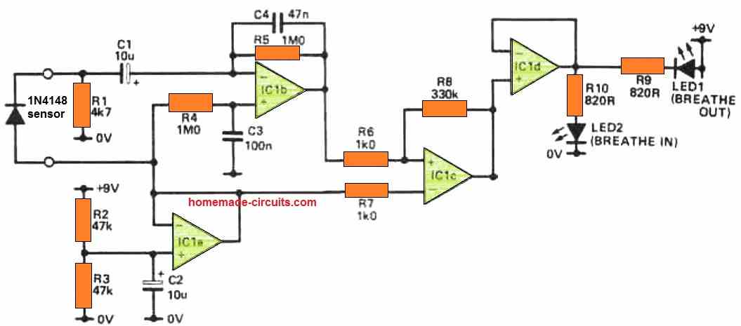
Hey, swagatam could you tell me what sort of a piezoelectric transducer I should use? Also tell the manufacturer's name if possible
Hi Uadyan,
Please see the image below: