• Skip to main content
  • Skip to primary sidebar

Homemade Circuit Projects

Need circuit help? Post them in the comments! I've answered over 50,000!

Blog | Categories | About | Hire Me | Contact | Calculators-online
You are here: Home / Datasheets and Components / OBD2 Connector Pinout, Datasheet

OBD2 Connector Pinout, Datasheet

Last Updated on May 17, 2026 by Swagatam 13 Comments

The DB9 to OBD-II adapter cable is an easy to use adapter that enables the EasySYNC range of CANbus products to fit compatibly with OBD-II interface connectors, typically utilized in automotive diagnostics.

Table of Contents
  • Understanding the Block Diagram
    • DB9 Connector (Female)
  • Cable Length
    • ODB-16P Connector (Male)
  • Internal Connection
  • Pinout Diagram of OBD-II adapter cable
    • Safety Definition
    • Environmental Specs

The DB9 pinouts directly fit into the EasySYNC CANPlus modules or any CANbus adapter which complies with the CAN-in-Automation (CiA) DS102-2 pin-out.
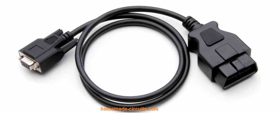
The OBD-II end can be directly plugged into any automotive diagnostic port. The cable specifically works with the CANbus portion of the OBD-II standards.

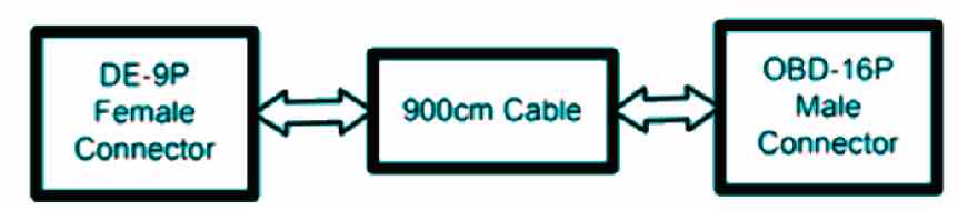
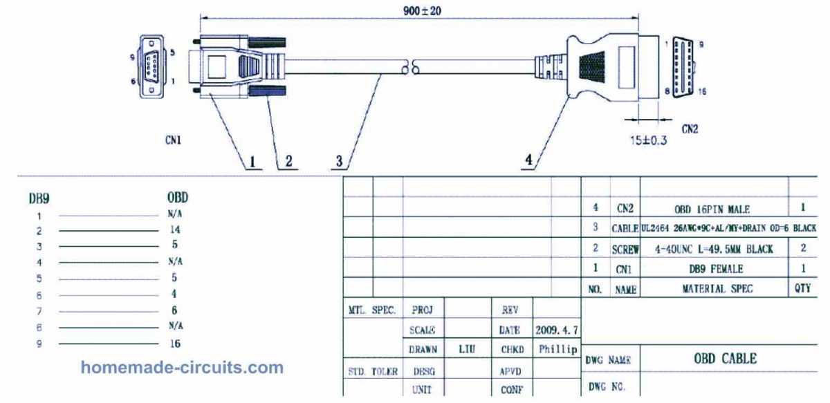
The Cable comes with a regular DB9 Female connector along with an OBD 16 Pin Male connector for executing the necessary communications across the EasySYNC CANbus products and OBD-II interface.

Understanding the Block Diagram
DB9 Connector (Female)

The DB9 connector is a female 9-way D-sub connector (also known as DE-9S) which can be wired directly fit with the EasySYNC CANPlus products. The signals transmitted from CANbus also comply with the standards of the CAN-in-Automation (CiA) DS102-2 pin-out.

Cable Length

The OBD-M-DB9-ES cord is 900mm long.

ODB-16P Connector (Male)

The wiring of the ODB-16P connector is designed such that it connects to the CANbus pins in an OBD-II automotive application.

Internal Connection

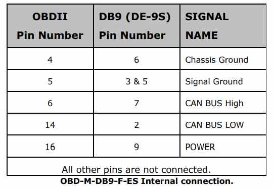
The following table below indicates how the wiring of the OBD-M-DB9-F-ES is implemented.
Pinout Diagram of OBD-II adapter cable
Safety Definition

The OBD-M-DB9-F-ES is specified within the Limited Power Supply (LPS) device category, designed to operate with voltages below 60VDC.

Environmental Specs

The OBD-M-DB9-F-ES is a lead-free product which conforms to the below given standard environmental guidlines:

RoHS, WEEE, REACH, PFOS and DecaBDE.
You'll also like:

  • LM3915 typical application circuitLM3915 IC Datasheet, Pinout, Application Circuits
  • 2N3055 power derating2N3055 Datasheet, Pinout, Application Circuits
  • 55V 110A N-Channel Mosfet IRF3205 Datasheet
  • IC IR2184, IR21844 Half-Bridge Driver Circuit Diagram, Datasheet, Working

Filed Under: Datasheets and Components Tagged With: Connector, Datasheet, OBD2, Pinout

About Swagatam

I am an electronics engineer and doing practical hands-on work from more than 15 years now. Building real circuits, testing them and also making PCB layouts by myself. I really love doing all these things like inventing something new, designing electronics and also helping other people like hobby guys who want to make their own cool circuits at home.

And that is the main reason why I started this website homemade-circuits.com, to share different types of circuit ideas..

If you are having any kind of doubt or question related to circuits then just write down your question in the comment box below, I am like always checking, so I guarantee I will reply you for sure!

Previous Post: « Ultrasonic Detector Circuit [Extend your Ear’s Sensitivity]
Next Post: Electromagnetic Levitation Circuit [Anti-gravity] »

Reader Interactions

Questions & Answers

Total Posts: 13
Newest Oldest
john
July 31, 2024 • 2 years ago #156561

I am looking for wire color to pinout for 2006 kia rio auto/ 1.6dohc base sedan obd2 connector . pins 4 and 5 are black gnd pin 16 is red power , The shell crumbled to particles in the dash , no schematic in any kia manual nor the dealership have been able to provide a color to pin diagram.
other wires are whiteish with yellow stripe , beige to yellow wire, 2 red wires with 2 different stripe colors 1 yellow the other blu, and 1 blue wire

Reply
SwagatamAdmin
August 1, 2024 • 2 years ago #156618

Although not sure, you may try investigating this page for the information:
https://www.automotive-manuals.net/kia/

Reply
john
August 1, 2024 • 2 years ago #156659

I have already tried this site as well as the official kia motors down loads. they do not have schematics that apply to the specific year nor doe the schematic include color of wires .
The schematic in the KIA motors manual only has 4 wires in it for the obd connector and the 2006 connector has 8 wires in it . not even the gnd or power wires match the 2006 .

Reply
SwagatamAdmin
August 2, 2024 • 2 years ago #156735

I checked Google again but could not find the exact information which you are looking for, seems like the manufacturer has not uploaded the information online.
I guess you should try posting your comment here:
https://www.kia-forums.com/threads/rear-speaker-wire-colors.331642/
I am sure you might already tried searching Youtube.
I hope you find the answers soon.

Reply
Blake Riley
July 30, 2024 • 2 years ago #156492

Hey, hoping I could find the pin out diagram with wire colors for a 2004 Jaguar XJ8. Not much luck so far. Thanks any help is appreciated.

Reply
SwagatamAdmin
July 30, 2024 • 2 years ago #156496

I found this pdf with some relevant information, though not sure if it has the required information in it:
http://www.jagrepair.com/images/Electrical/XJElectrical/2004%20MY%20XJ%20Electrical%20Guide.pdf

Reply
Rikki herszman
August 18, 2023 • 3 years ago #144765

Hi im trying to figure out pin wise since I already have some supplies on how to adapt my obd2 male end cable to a 25 pin male dsub connector so that I can use this adapter I have that’s 25 pin dsub female on one side and obd1 ford connector on the otherwise basically allowing me to plug my obd2 tool into a 91 ford f250 wich has the obd1 port..so I need to go from obd2 male to 25 pin dsub I appreciate your help and if u know how to go from obd 2 male to obd1 gm that would be greatly appreciated also thanks…rick

Reply
SwagatamAdmin
August 18, 2023 • 3 years ago #144768

Hi, although I am not entirely sure how to solve your query, I have some general suggestions which you might find helpful:

For the OBD2 to 25-pin D-sub adapter:

Identify Pins: Find a pinout diagram for both the OBD2 male connector and the 25-pin D-sub connector. This will help you match the corresponding pins between the two connectors.

Wire Connection: You will need to map the OBD2 pins to the appropriate pins on the 25-pin D-sub connector. This may require soldering or crimping wires to create the connections.

Signal Compatibility: Check the signal compatibility between the OBD2 and the older OBD1 Ford port. If there are differences in data protocols or signal voltages, you might need additional circuitry to convert signals appropriately.

For the OBD2 to OBD1 GM adapter:

Adapting from OBD2 to OBD1 can be more complex due to differences in communication protocols and pin assignments. It may not be a straightforward process and might require additional circuitry or conversion.

Reply
Steven Schaefer
July 18, 2022 • 4 years ago #131681

Is there an adapter that allows use of arinc 429 to canbus, in & out?

Reply
SwagatamAdmin
July 19, 2022 • 4 years ago #131693

Sorry, no ideas about it!

Reply
Rafael
October 5, 2021 • 5 years ago #99768

Is there a software to connect via PC?

Reply
SwagatamAdmin
October 5, 2021 • 5 years ago #99805

Sorry I have no idea about it!

Reply
Rafael
October 5, 2021 • 5 years ago #99858

Thank you for your fast response

Reply

Need Help? Please Leave a Comment! We value your input—Kindly keep it relevant to the above topic! Cancel reply

Your email address will not be published. Required fields are marked *

Primary Sidebar

My YouTube Channel

Circuit Simulator: Draw and Simulate Schematics

circuit simulator image

Categories

  • Arduino Projects (95)
  • Audio and Amplifier Projects (134)
  • Automation Projects (18)
  • Automobile Electronics (104)
  • Battery Charger Circuits (90)
  • Datasheets and Components (109)
  • Electronics Theory (151)
  • Energy from Magnets and Earth (43)
  • Games and Sports Projects (11)
  • Grid and 3-Phase (20)
  • Health related Projects (27)
  • Home Electrical Circuits (13)
  • Indicator Circuits (16)
  • Inverter Circuits (98)
  • Lamps and Lights (161)
  • Meters and Testers (72)
  • Mini Projects (28)
  • Motor Controller (68)
  • Oscillator Circuits (30)
  • Pets and Pests (15)
  • Power Supply Circuits (91)
  • Remote Control Circuits (50)
  • Security and Alarm (65)
  • Sensors and Detectors (107)
  • SMPS and Converters (46)
  • Solar Controller Circuits (62)
  • Temperature Controllers (44)
  • Timer and Delay Relay (51)
  • Voltage Control and Protection (44)
  • Water Controller (37)
  • Wireless Circuits (31)

Subscribe to get New Circuits in your Email

Other Links

  • Privacy Policy
  • Cookie Policy
  • Disclaimer
  • Copyright
  • Videos
  • Sitemap

People also Search

555 Circuits | 741 Circuits | LM324 Circuits | LM338 Circuits | 4017 Circuits | Ultrasonic Projects | SMPS Projects | Christmas Projects | MOSFETs | Radio Circuits | Laser Circuits | PIR Projects |

Recent Comments

  • Swagatam on EGS002 Datasheet, Circuit Diagram Explained
  • Hung on EGS002 Datasheet, Circuit Diagram Explained
  • Swagatam on How to Design a Buck Converter Circuit: Formulas and Calculations
  • martin on How to Design a Buck Converter Circuit: Formulas and Calculations
  • Swagatam on Touch Dimmable LED Light Bar Circuit

Social Profiles

  • Twitter
  • YouTube
  • Instagram
  • Pinterest
  • My Facebook-Page
  • Stack Exchange
  • Linkedin

Calculators

  • ZVS Induction Heater + Tank Calculator Tool
  • Zener Diode Calculator
  • Wire Current and Thickness Calculator (Ampacity Calculator)
  • Voltage Divider Calculator
  • Transistor Base Resistor Calculator
  • Transistor Astable Multivibrator Calculator
  • TL431 Calculator
  • Solar Panel, Inverter, Battery Calculator
  • Ferrite Core Air Gap Calculator Tool
  • Parallel MOSFET Calculator Tool: How to Connect MOSFETs in Parallel Safely
  • LC Resonance Calculator for EV Battery Charger Circuits
  • LED String Series Resistor Calculator
  • PFC (Power Factor Correction) Calculator Tool: 3kW
  • Passive Power Factor Correction (PFC) Calculator
  • LM567 IC Calculator Tool
  • SMPS Flyback Boost Converter Calculator
  • Shunt Resistor Calculator for Ammeters
  • SCR and Triac Gate Resistor Calculator
  • Battery Back up Time Calculator
  • Boost Converter Calculator (Non-Isolated)
  • Bootstrap Capacitor Calculator
  • Buck Converter Calculator
  • Buck-Boost Converter Calculator
  • Capacitance Reactance Calculator
  • DCM Flyback Transformer & Wire Gauge Wire Size Calculator Tool
  • Filter Capacitor Calculator
  • IC 4047 Calculator (Frequency and PWM)
  • IC 4060 Calculator
  • IC 555 Astable Calculator
  • IC 555 Monostable Calculator
  • IC SG3525, SG3524 Calculator
  • Inductance Calculator
  • Induction Heater Inductor and Resonant Frequency Calculator
  • Induction Heater Work Coil Calculator
  • Inverter LC Filter Calculator
  • LC Resonance Calculator
  • LED Current Calculator
  • LM317, LM338, LM396 Calculator
  • NAND/NOT Gate RC Values Calculator
  • NOT, NAND Gate Frequency Calculator
  • Notch Filter Calculator Tool
  • Ohm’s Law Calculator
  • Phase Angle Phase Shift Calculator
  • Power Factor (PF) Calculator
  • RC Filter Calculator
  • Reactance Calculator
  • Sine Table Calculator for SPWM Arduino Code
  • Small Signal Transistor(BJT) and Diode Quick Datasheet
  • SMPS Calculator for Toroidal Ferrite Transformers
  • SMPS Flyback Transformer Calculator – Design by Target Duty Cycle
  • TL431 Calculator
  • Op-Amp Hysteresis Resistor Calculator

© 2026 · Swagatam Innovations