The ultrasonic detector or receiver circuit will be able to detect all those high frequency sounds that are beyond the hearing capacity of humans.
The units will be able to hear all those frequencies that are perhaps only audible to some animals like dogs, cats and bats. The ultrasonic receiver circuit can be used for enhancing or extending the hearing capability of a human being to levels which are not feasible to the normal ear.
How the Circuit Works
Referring to the circuit diagram shown below, the piezo speaker, MIC1, is formed by a piezo electric transducer.
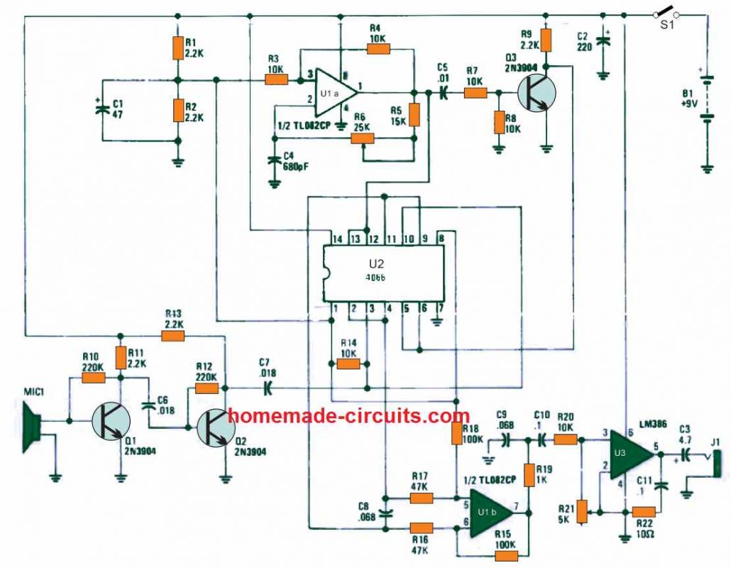
The device detects the inbound ultrasonic signal and passes it to the base terminal of the transistor Q1. The two-transistor stage using Q1 and Q2 works like a booster amplifier stage which elevates the detected ultrasonic signals to an amount which is enough to trigger the single input of a very unconventional mixer circuit.
The IC U2 which is a quad bilateral switch operates like an exceptionally clean balanced-mixer circuit intended for the superheterodyne receiver. IC U1a is configured like a variable-frequency squarewave-oscillator circuit. Resistors R5, R6, and capacitor C4 are configured to fix the frequency and tuning range of the oscillator stage.
The squarewave signal from the oscillator stage is directed across a a couple of tracks. In one track, the U1a output becomes the input for the pins12 and pin13 of U2. In the second track, the signal goes to the Q3 base, constructed like an inverter.
This inverter generates a signal output which is 180° out of phase with the input signal. This out of phase signal from of Q3 is then applied to U2 at its pins 5 and 6.
At these pinouts of the op amp the two input signals which are one ultrasonic input originating from MIC1 while the other from the oscillator output are mixed together. This mixing of the ultrasonic signal from the MIC with the oscillator's square-wave causes the generation of an audible combination which is then applied to the input of a differential amplifier UIb, which is configured to provide a voltage gain of 2.
The U1b output available at pin 7 is subsequently filtered and cleaned by the resistors R19 and C9 to eliminate the high frequency material of the mixed signal.
Since it is only the difference frequency that matters, the sum frequency (the inbound ultrasonic signal added to the oscillator frequency), that may be excessively high for our ear to hear, is eradicated by R19 and C9 to provide a thoroughly clean and filtered output signal.
This cleaned up output is finally supplied to the power amplifier U3. Resistor R21 is configured to work like the circuit's volume control.
How to Test and Use
The testing and using the proposed ultrasonic receiver circuit can be done with the help of the following steps:
Swith ON power to the circuit, adjust the knobs of the volume and tuning controls to their mid-way placement. Next with the headphones fixed over your ears, start rubbing your fingers together just near the piezo transducer speaker. If everything is fine with the circuit, the rubbing of the fingers must sound like a sandpaper being brushed over a hard surface.
For the next test procedure, get hold of some small metal screws in your, along with a few nuts, and washers, then shuffle them inside your folded fingers near the piezo transducer. You may find this sound like huge metals pipes banging across each other.
While implementing the above testing procedures, make sure to keep adjusting the tuning potentiometer until your ear starts hearing full of abnormal and strange sound effects.
The tuning range of the oscillator circuit stage could be anywhere between 15 kHz and 35 kHz. This frequency range permits the user to hear external ultrasonic sounds between 15 kHz to near and above 40 kHz.
Normally, it becomes impossible for us to hear sounds above 15 kHz, but with this ultrasonic detector circuit you would be able to hear all the sounds ranging above 15 kHz and even up to 40 kHz frequencies.
Ultrasonic Receiver using IC 4046
The following ultrasonic receiver circuit allows you to hear ultrasonic sounds, much like dogs, bats, and other animals. Besides its recreational interest, this device allows for a number of interesting experiments in various fields.
For example, in spelunking or exploring caves, you can effectively detect the presence of bats, which, as everyone knows, use ultrasonic sounds similar to sonar used by submarines to navigate.
If you are a hunter, you can verify the effectiveness of your brand new ultrasonic whistle in calling back your faithful four-legged companion.
Lastly, if you suffer from persistent and unidentified headaches, you can check if the environment you're in contains a powerful ultrasonic source, as these can have effects on our bodies and potentially be the cause of your headaches.
Circuit Description
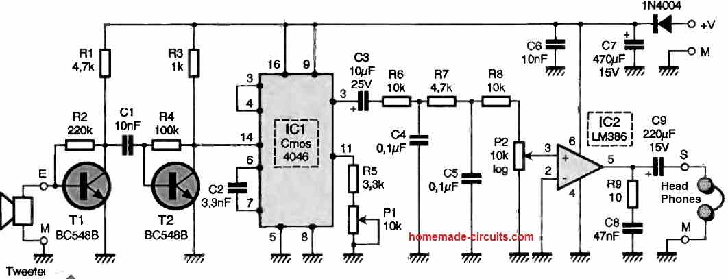
The ultrasonic signals captured by the microphone are greatly amplified using amplifiers T1 and T2 before being applied to IC 4046, which is nothing other than a phase-locked loop in CMOS technology.
The operating frequency of its internal VCO (Voltage-Controlled Oscillator) is adjusted using potentiometer Pi, and the circuit operates here as a frequency mixer.
Therefore, at its output pin 2, we have a signal whose frequency is the difference between the frequency of the ultrasonic signal and that of the internal VCO.
If our ultrasonic signal is at 25 kHz and the VCO is set to 20 kHz using P1, we will have an output signal at 5 kHz, which is perfectly audible.
This signal is then filtered by R6, R7, C4, and C5 to remove any remaining high-frequency residues it may contain before being amplified by IC2, a classic LM386 amplifier, which is more than powerful enough for such an application.
Construction
The printed circuit board provided supports all components, including potentiometers, to facilitate assembly.
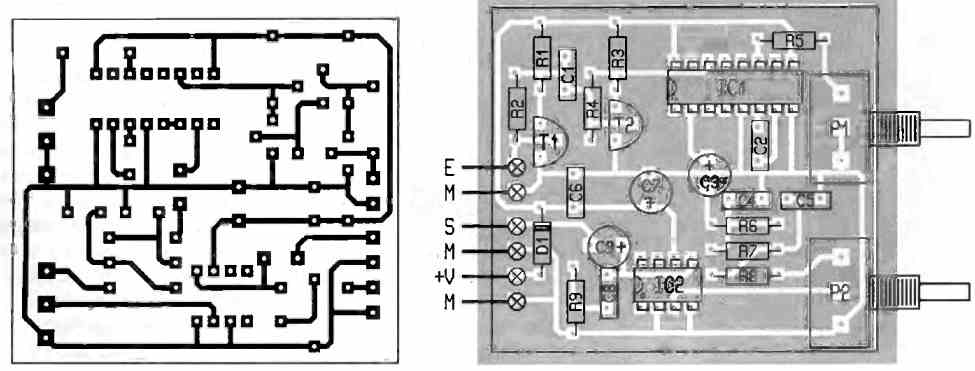
The potentiometers are standard, except for the ultrasonic microphone, which you can experiment with. As for us, we obtained good results with a piezo tweeter capable of reaching up to 30 kHz.
Some authors recommend using traditional ultrasonic transducers used in alarms and remote controls for similar projects.
However, these components have the drawback, in our opinion, of having a fairly precise resonance frequency (40 kHz in this case) and therefore being less sensitive when deviating from that frequency.
Nevertheless, we leave it up to you to conduct your own experiments in this area because neither these transducers nor inexpensive piezo tweeters (a hi-fi model is unnecessary) are expensive.
The power supply can be provided by a 9V mains adapter for fixed use, while a 9V alkaline battery ensures many hours of mobility, with power consumption ranging from a few mA to tens of mA depending on the listening volume.
In the latter case, diode D1 can be omitted and replaced with an on/off switch.
Using an Headphone
Preferably, the sound will be listened to using headphones rather than a speaker. Any inexpensive headphones for portable devices will do.
Since these models are always stereophonic, you should wire both earpieces in series so that they work simultaneously.
Furthermore, this series wiring reduces the power that IC1 may deliver and thus decreases the circuit's power consumption.
How to Use
The usage is straightforward and can be summarized as follows: after adjusting the volume, manipulate P1 to vary the VCO frequency.
The range of useful ultrasonic frequencies is quite wide, from approximately 18 kHz to 60 kHz, and cannot be fully covered by a single position of P1.
Keep in mind that the "microphone" used, whether an ultrasonic transducer or a piezo tweeter, is quite directional, as are certain ultrasonic transmitters. Happy exploring!


Questions & Answers
hi, i need to listen to 30khz analog signal. main piezo are for 40khz with a narrow bandwidth. do you know where to get different frequency response ?
yes, those 40kHz piezos are too sharp tuned, they cannot catch 30kHz nicely. You need wideband ultrasonic mic or real 30kHz resonant piezo. You can try ultrasonic mic capsules or those used in bat detectors, which work from 20kHz to 100kHz easy. Normal 40kHz type will stay mostly deaf around 30kHz.
Dear Swagatam
I would like to start by thanking you very much for your sharing. I am interested in ultrasonic water level meters. Multilayer amplifiers are used in their working principles. what I want, I need a circuit that I can measure the distance “cm or mm” with the reflection technique up to a distance of 10 meters working in the 40Khz frequency band. I would be very grateful if you could help me with this. Greetings…
Thank you so much Mert, for your kind words.
Although I have a similar looking circuit in this blog, the circuit provides the distance only through 4 LEDs which might not be so accurate. Here’s the link of the article.
https://www.homemade-circuits.com/ultrasonic-fuel-sensor-circuit/
Your application will specifically require an Arduino circuit, and unfortunately I am not good with Arduino programming so creating a customized design may be beyond the reach of my expertise.
However, you can perhaps ask Google-Gemini to improve the code provided in the above article as per your needs and check the results.
f06-09-2023
(1.) Hi, there.
(2.) New to electronics.
(3.) For the following electrolytic capacitors, would you indicate the unit of measurement, the voltage, the type/style (Mylar, box, polypropylene, etc.):
(3a.) .01
(3b.) .1
(3c.) .018
(3d.) .068
(3e.) 220
(3f.) 4.7
(3g.) 47
(4.) Also, would you add breadboards to your circuits? { Helps a whole lot when you’re a newbie and trying to decipher the circuit diagrams. }
(5.) Thanks.
(6.) Toodles!
Hi, the unit of measurement for all these capacitors is microfarad (uF)
All capacitors equal or above 1uF are electrolytic and which are below 1uF can be disc ceramic or polypropylene.
Adding breadboard wiring details can be a lot of work, and anyway I don’t recommend breadboard which can give connection errors…the best way is to build by soldering on a stripboard.
sa06-10-2023
(1.) Hi, there.
(2.) Appreciate the information on the UoM and such.
(3.) Does the voltage matter when using capacitors——electrolytic or otherwise?
{ Kit I bought has some of the electrolytic capacitors in there with equal values, but different with voltages, so just want to be sure for this circuit. }
(4.) Thanks.
(5.) Toodles!
As a rule of thumb the voltage of a capacitor should be ideally two times the supply voltage of the circuit, if it is higher, no issues, but should not be lower than 1.5 times the supply level.
r04-30-2026
Hi, there.
Not understanding how to properly connect:
P1…Does the wiper for this 10K potentiometer connect to the 3.3K resistor?
P2…How is this 10K potentiometer different than the one used in P1? What does the logarithmic component mean?
Thanks so much!
Hey,
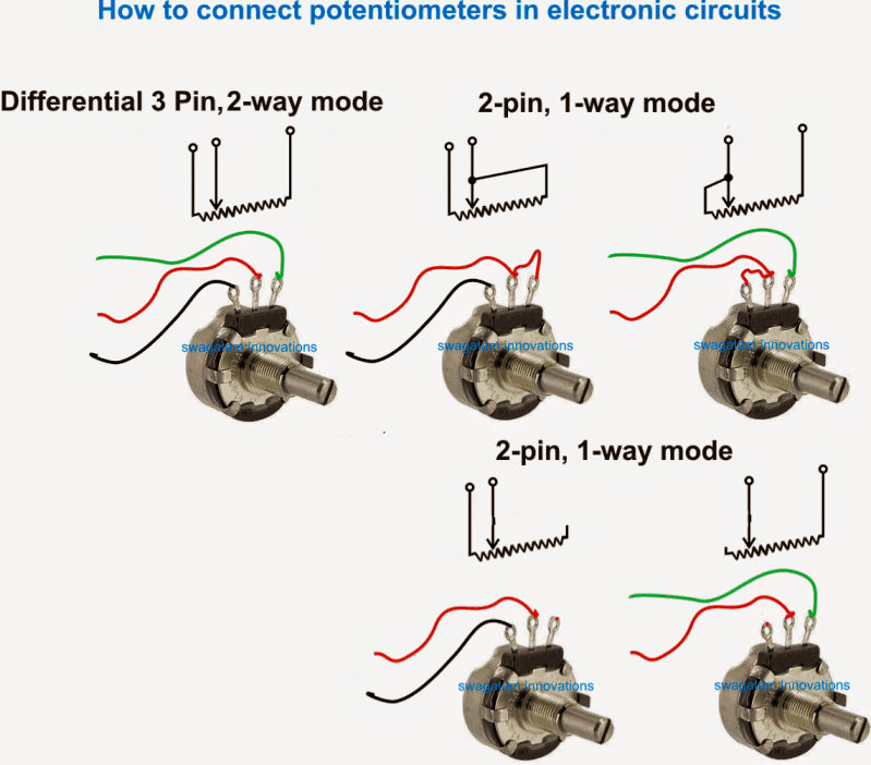
please check this diagram, and you can compare and understand the configurations.
One pot is 10k log, while the other default pot is 10k linear, log variation is not linear, while the linear one is linear.
Hello
what is J meaning of electronics
Joule symbol
Hello, Mr. Engineer, I am interested in this circuit, can you share the chip used in the circuit, I can’t see what it is.
The opamps are from the IC TL082, and the other IC is 4066