In this post I have explained how to build an electromagnetic levitation circuit which can imitate an anti-gravity phenomenon by ensuring that an iron object remains pulled above the ground by an electromagnet, so that it does not stick to the electromagnet, rather keeps floating between the electromagnet tip and the ground.
Basic Working Principle
An LDR, LED combination is utilized in such a way that the LED beam passes from just under the electromagnet and illuminated the LDR. In this situation as long as the LDR remains illuminated, the electromagnet stays functional and its electromagnetic power remains activated.
When an iron object is held just below the electromagnet, it starts getting pulled towards the electromagnet, but in the process it cuts off the LED beam reaching the LDR, which switches OFF the electromagnet.
When this happens the iron object begins dropping, but again in doing so it begins moving away from the path of the LED beam and allows the light to reach the LDR.
This situation switches ON the electromagnet back, so that the iron object again starts getting pulled towards the electromagnet, and this up down cycle repeats rapidly, creating a condition where the iron object is neither completely pulled by the electromagnet nor is completely dropped to the ground. The situation keeps the iron object floating in mid air, maybe a few mm under the electromagnet, giving the appearance of an anti-gravity levitation effect.
How to Build
The levitation set up can be best built using pieces of wooden blocks, and framing them in the following manner:
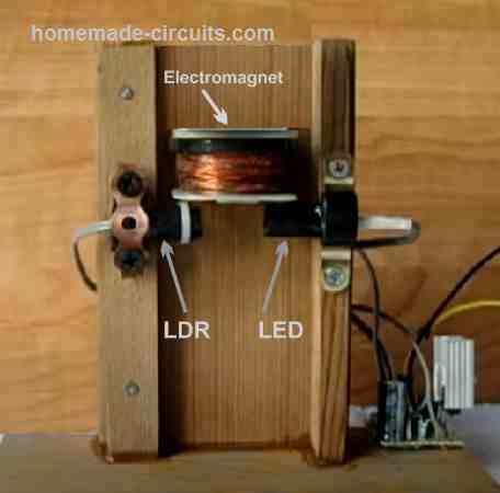
In this set up we can see the electromagnet fixed at the upper center area of the wooden structures, while the LED and LDR are positioned face to face over the adjacent upright wooden structures, just below the electromagnet.
It is important that the LED and the LDR are placed inside an opaque plastic tubes to ensure that only the LED light beam enters the LDR tube and illuminates it, and no other external ambient light is able to reach the LDR.
Once the electromagnetic levitation circuit is powered ON, the LED illuminates and hits the LDR, which causes the electromagnet to switch ON.
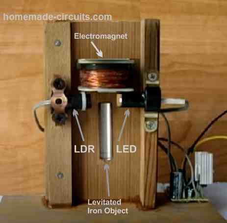
Now, the electromagnet being switched ON, if a iron object is brought near the electromagnet will cause the object to be pulled towards the electromagnet.
However, during this process the iron object wil tend to block the LED beam from the reaching the LDR. This will instantly cause the electromagnet to switch OFF. As soon as this happens the iron object will tend to fall down, but in the process will move away from the LED beam illuminating the LDR and switching ON the electromagnet back in action. This rapid ON/OFF process of the electromagnet will cause the iron object to remains hanging just below the electromagnet creating an impression of a true levitation or anti-gravity effect, as shown in the following image.
How the Circuit Works
The circuit for the levitation system can be viewed in the following diagram:
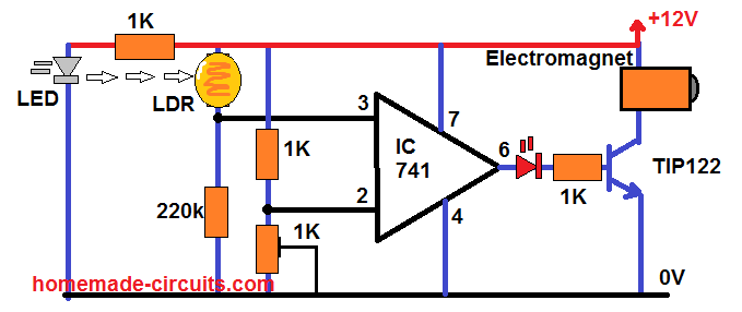
As you can see there's hardly any components in the design, and the entire circuit is built around a single IC 741 which is configured like a comparator.
The pin#2 of the op amp is fixed with a constant reference voltage using the preset 1k. This reference voltage is not very critical, since the LDR switching is either ON or OFF.
The LED light can be seen focused on the LDR as explained in our previous construction set of the unit.
During the time the light remains focused on the LDR, its resistance drops to a much lower level, causing the pin#3 potential of the op amp to rise above the pin#2 reference potential as fixed by the 1k preset.
Due to this the output of the op amp remains high, enabling the electromagnet to remain activated.
As discussed in the previous paragraphs, when the iron object is pulled towards the electromagnet, in the process it attempts to block the LED beams reaching the LDR.
When this happens, the pin#3 potential drops below the pin#2 reference potential which now rises above the pin#3 potential. Due to this, the pin#6 output of the op amp turns off, which also turns off the driver transistor and the electromagnet.
This instantaneous switching off of the electromagnet tends to drop the iron object, which causes the LDR to again get illuminated by the LDR beam, which reverts the op amp output high, switching ON the electromagnet back, so that the iron objetc s again pulled up. This pulling and dropping process of the iron object continuous at an extremely fast rate causing, such that the the object appears to remains stationery just below the electromagnet, which gives an impression of the object being levitated, and it is hanging in mid-air due to anti-gravity effect.
How to Build the Electromagnet
The electromagnet can be by built by winding a 120 grams of 28 SWG super enameled wire over any thick iron bolt. Make sure to insulate the iron bolt with a couple of layers of insulating PVC tape before you start winding the coil.
If you are unable to built the above mentioned electromagnet, you can simply salvage the relay coil from any old 12V, 30 amp relay.
Advantage of Using LED/LDR for the Sensor
There are many electromagnet levitation circuits available online which uses an infrared photodiode as the sensor. However, selecting the correct photodiode may not be easy for new hobbyists, and also the results obtained from photodiode may sometimes have issues.
Using LDR/LED combination is more advantageous since they are easily available and do not have strict specifications. You can choose just about any tiny LDR, and a tiny 3.3 V white LED, that's all and you are good to go.
Another advantage of using an LED is that, the light from the LED illuminates the area just under the electromagnet creating a fascinating effect on the levitated iron object.


Questions & Answers
Hello Swagatam,
I really appreciate your help if you design a circuit for repulsive Electromagnetic Levitation.
Thank you hejazi, I get the necessary circuit details, I will surely update it in this website….