• Skip to main content
  • Skip to primary sidebar

Homemade Circuit Projects

Need circuit help? Post them in the comments! I've answered over 50,000!

Blog | Categories | About | Hire Me | Contact | Calculators-online
You are here: Home / Automobile Electronics / Motorcycle Regulator, Rectifier Tester Circuit

Motorcycle Regulator, Rectifier Tester Circuit

Last Updated on May 16, 2026 by Swagatam 1 Comment

The motorcycle regulator, rectifier tester circuit presented here can be used to test a 6-wire shunt type regulator-rectifiers for a 3-phase charging system of motorcycles. These reg./rectifiers (RR-units) are usually sealed with epoxy and it is considered difficult to find out if the unit is faulty or not.

Table of Contents
  • REGULATOR TESTER:
  • RECTIFIER TESTER:

Designed and Written by: Abu-Hafss

As the name suggests, the unit consists of 2 circuits i.e. the Regulator and the Rectifier. Usually, the wires are coded as below:

Red = BATTERY +

Green = EARTH (Chassis or Battery -)

Black/Yellow = IGNITION

3 Yellow or 3 Pink = 3 PHASES
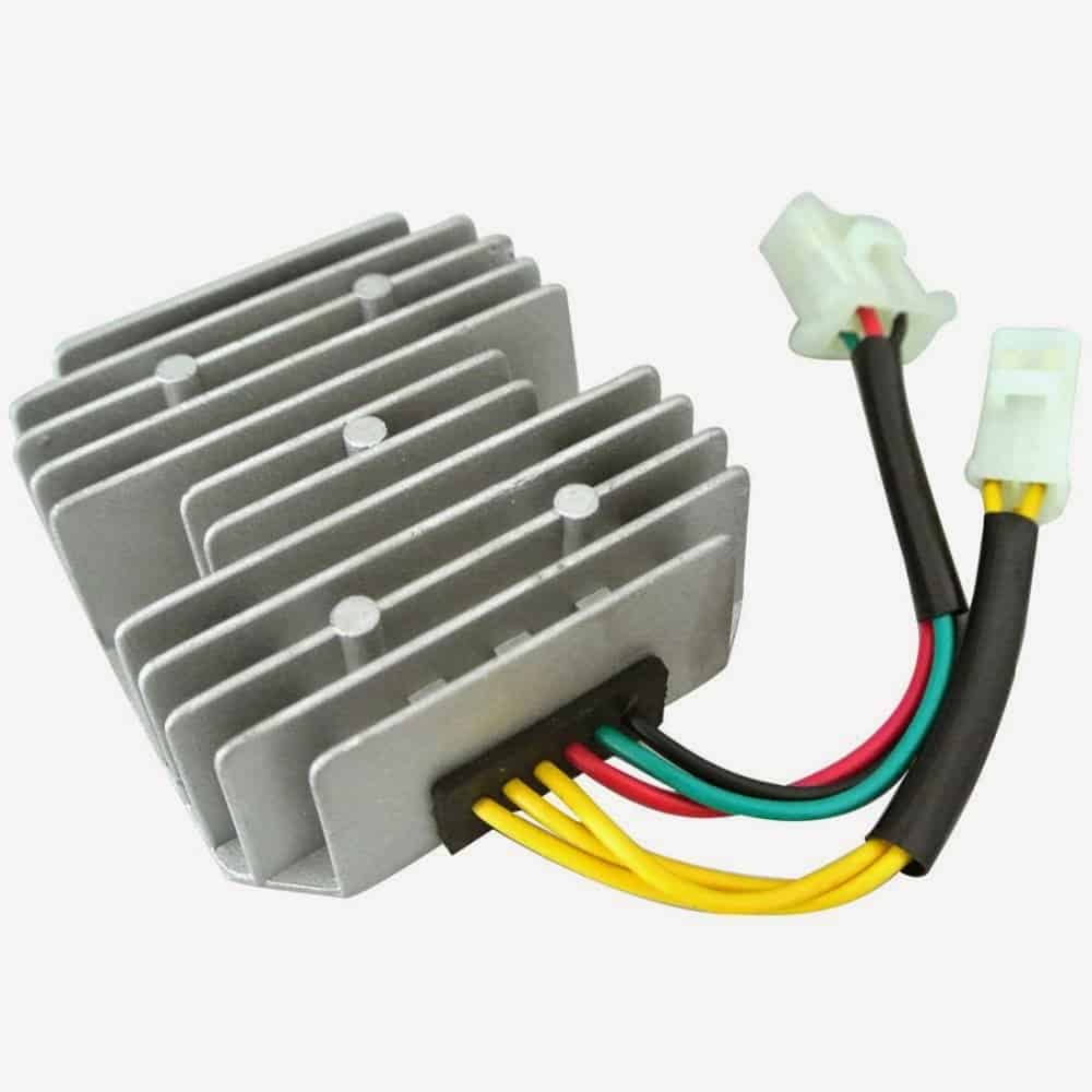
readymade motorcycle rectifier regulator

To test those 2 circuits, the tester circuit is also divided accordingly.

REGULATOR TESTER:

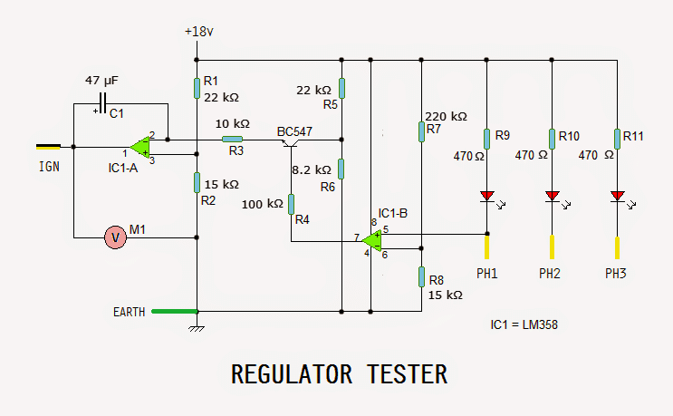
To test the Regulator, its wires are connected to the test circuit as shown. The red wire is not used.
Motorcycle Regulator, Rectifier Tester Circuit

Initially Q1 is on, hence a ramp voltage is generated from about 7V to about 16.5V. This ramp is fed into the RR-unit via its IGNITION wire (BLACK/YELLOW).

At the same time, voltage from one of the phases is fed into pin# 5 of IC1-B which is configured as voltage comparator. It compares it with the reference voltage assigned by voltage divider R7 & R8. Since the voltage at pin#5 is lower than the ref. voltage at pin# 6, the output at pin# 7 becomes low.

This switches off Q1 thereby cutting off the ramp-triggering voltage. The ramp voltage comes to a halt. This regulated voltage (14.4 - 15V) can be read with voltmeter M1.

If any of the LEDs does not light up or none of the LEDs light up, it indicates that one or more SCRs are bad. If the voltmeter reads around 16.5V, it indicates the regulator circuit is not working.

RECTIFIER TESTER:

The rectifier section of RR-unit consists of only 6 rectifier diodes as shown. The wires are connected as shown. The Black/Yellow wire is not used.
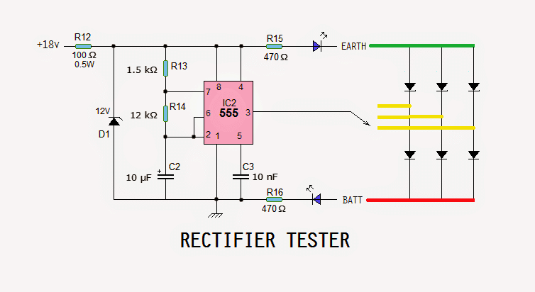
IC2 is a 555 which is configured as an astable vibrator. Since the supply voltage is 18V and max voltage for 555 is 15V, a zener diode D2 is introduced to protect the IC.

The output is connected to 1 yellow wire at a time. Both the LEDs should blink, indicating that the corresponding rectifiers are good. If only one LED or no LED blinks, it indicates one or both rectifiers are bad.

Now, the connections of red and green wires are interchanged. If one or both LEDs blink, it indicates that the rectifiers are short (bad).

p.s. I have tested the above explained motorcycle regulator, rectifier tester circuit
-Abu Hafss
You'll also like:

  • reverse horn PCB trackCar Reverse Horn Circuit
  • Automotive Trailer Lights Interface Circuit
  • enhanced CDIElectronic 12V DC Capacitive Discharge Ignition (CDI) Circuits
  • Simple Car Burglar Alarm Circuit

Filed Under: Automobile Electronics Tagged With: Motorcycle, Rectifier, Regulator, Tester

About Swagatam

I am an electronics engineer and doing practical hands-on work from more than 15 years now. Building real circuits, testing them and also making PCB layouts by myself. I really love doing all these things like inventing something new, designing electronics and also helping other people like hobby guys who want to make their own cool circuits at home.

And that is the main reason why I started this website homemade-circuits.com, to share different types of circuit ideas..

If you are having any kind of doubt or question related to circuits then just write down your question in the comment box below, I am like always checking, so I guarantee I will reply you for sure!

Previous Post: « Remote Controlled Fish Feeder Circuit – Solenoid Controlled
Next Post: Submersible Pump Start/Stop Circuit »

Reader Interactions

Questions & Answers

Total Posts: 1
Newest Oldest
salman
December 29, 2020 • 6 years ago #85713

i want this i have renegade commando bike

Reply

Need Help? Please Leave a Comment! We value your input—Kindly keep it relevant to the above topic! Cancel reply

Your email address will not be published. Required fields are marked *

Primary Sidebar

My YouTube Channel

Circuit Simulator: Draw and Simulate Schematics

circuit simulator image

Categories

  • Arduino Projects (95)
  • Audio and Amplifier Projects (134)
  • Automation Projects (18)
  • Automobile Electronics (104)
  • Battery Charger Circuits (90)
  • Datasheets and Components (109)
  • Electronics Theory (151)
  • Energy from Magnets and Earth (43)
  • Games and Sports Projects (11)
  • Grid and 3-Phase (20)
  • Health related Projects (27)
  • Home Electrical Circuits (13)
  • Indicator Circuits (16)
  • Inverter Circuits (98)
  • Lamps and Lights (161)
  • Meters and Testers (72)
  • Mini Projects (28)
  • Motor Controller (68)
  • Oscillator Circuits (30)
  • Pets and Pests (15)
  • Power Supply Circuits (91)
  • Remote Control Circuits (50)
  • Security and Alarm (65)
  • Sensors and Detectors (107)
  • SMPS and Converters (46)
  • Solar Controller Circuits (62)
  • Temperature Controllers (44)
  • Timer and Delay Relay (51)
  • Voltage Control and Protection (44)
  • Water Controller (37)
  • Wireless Circuits (31)

Subscribe to get New Circuits in your Email

Other Links

  • Privacy Policy
  • Cookie Policy
  • Disclaimer
  • Copyright
  • Videos
  • Sitemap

People also Search

555 Circuits | 741 Circuits | LM324 Circuits | LM338 Circuits | 4017 Circuits | Ultrasonic Projects | SMPS Projects | Christmas Projects | MOSFETs | Radio Circuits | Laser Circuits | PIR Projects |

Recent Comments

  • Swagatam on Electronic Circuit Projects, Tutorials, and Practical Engineering Solutions
  • Swagatam on Simplest Full Bridge Inverter Circuit
  • Amal on Simplest Full Bridge Inverter Circuit
  • Michael on Electronic Circuit Projects, Tutorials, and Practical Engineering Solutions
  • Swagatam on Electronic Circuit Projects, Tutorials, and Practical Engineering Solutions

Social Profiles

  • Twitter
  • YouTube
  • Instagram
  • Pinterest
  • My Facebook-Page
  • Stack Exchange
  • Linkedin

Calculators

  • ZVS Induction Heater + Tank Calculator Tool
  • Zener Diode Calculator
  • Wire Current and Thickness Calculator (Ampacity Calculator)
  • Voltage Divider Calculator
  • Transistor Base Resistor Calculator
  • Transistor Astable Multivibrator Calculator
  • TL431 Calculator
  • Solar Panel, Inverter, Battery Calculator
  • Ferrite Core Air Gap Calculator Tool
  • Parallel MOSFET Calculator Tool: How to Connect MOSFETs in Parallel Safely
  • LC Resonance Calculator for EV Battery Charger Circuits
  • LED String Series Resistor Calculator
  • PFC (Power Factor Correction) Calculator Tool: 3kW
  • Passive Power Factor Correction (PFC) Calculator
  • LM567 IC Calculator Tool
  • SMPS Flyback Boost Converter Calculator
  • Shunt Resistor Calculator for Ammeters
  • SCR and Triac Gate Resistor Calculator
  • Battery Back up Time Calculator
  • Boost Converter Calculator (Non-Isolated)
  • Bootstrap Capacitor Calculator
  • Buck Converter Calculator
  • Buck-Boost Converter Calculator
  • Capacitance Reactance Calculator
  • DCM Flyback Transformer & Wire Gauge Wire Size Calculator Tool
  • Filter Capacitor Calculator
  • IC 4047 Calculator (Frequency and PWM)
  • IC 4060 Calculator
  • IC 555 Astable Calculator
  • IC 555 Monostable Calculator
  • IC SG3525, SG3524 Calculator
  • Inductance Calculator
  • Induction Heater Inductor and Resonant Frequency Calculator
  • Induction Heater Work Coil Calculator
  • Inverter LC Filter Calculator
  • LC Resonance Calculator
  • LED Current Calculator
  • LM317, LM338, LM396 Calculator
  • NAND/NOT Gate RC Values Calculator
  • NOT, NAND Gate Frequency Calculator
  • Notch Filter Calculator Tool
  • Ohm’s Law Calculator
  • Phase Angle Phase Shift Calculator
  • Power Factor (PF) Calculator
  • RC Filter Calculator
  • Reactance Calculator
  • Sine Table Calculator for SPWM Arduino Code
  • Small Signal Transistor(BJT) and Diode Quick Datasheet
  • SMPS Calculator for Toroidal Ferrite Transformers
  • SMPS Flyback Transformer Calculator – Design by Target Duty Cycle
  • TL431 Calculator
  • Op-Amp Hysteresis Resistor Calculator

© 2026 · Swagatam Innovations