In this design a solenoid is operated using an IR remote control, which in turn toggles the fish feeder mechanism.
In this article I have explained how to make a simple infrared controlled fish feeder circuit. The idea was requested by Mr. Harishvar.
Technical Specifications
I just want a circuit which should turn on when i press and hold a key from my remote. my use is: i have a motor as a vibrator and i have fixed it near my aquarium tank.
i just want to trigger the motor whenever i press a key from a particular remote i.e. if i press a key and hold it the motor should be on and as soon as i release the key the motor should be off, actually i have attached the motor to a container containing fish food.
if i press the remote the motor should be on due to which the container will vibrate and food will fall into the tank and as soon a s i leave the button the motor should be off.
this is the main aim of circuit....and also sir the motor should be triggered only with a particular kind of remote...so plzz design a circuit for the
remote also...the motor should not be triggered with any other remote, instead it should be triggered only with the unique remote that you should design, so please give the circuit as soon as possible....thank you
I just want a remote and a receiver, if i press the button on the remote the receiver should trigger the motor as long as i keep the button pressed, you may take the range any value.
if i sit on my sofa and operate, it should operate. My sofa and my aquarium tank has about the distance of 5 meters so do it anyway you want.
i just want the circuit to be working that's all and also sir plxx make use of the components that are easily available and plzz make it as simple as possible....
The Design
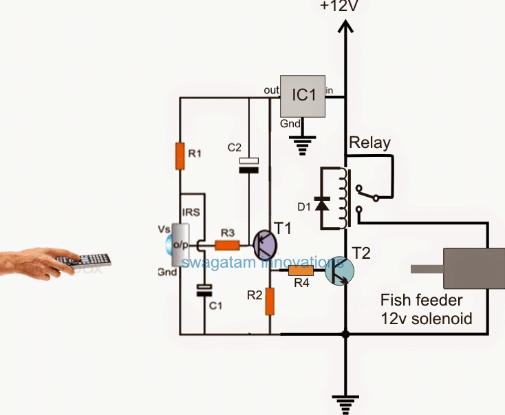
The following diagram shows the basic circuit layout for the proposed remote controlled fish feeder circuit.
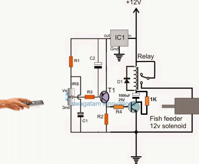
A rough Simulation of the above requested circuit can be witnessed below:
The above presented simulation of the proposed remote controlled fish feeder circuit can be realized with the help of the following points:
For ensuring 100% safety to the solenoid and the circuit, it is recommended to add a 1000uF capacitor network at the collector of the relay driver transistor. This will ensure that the relay never stays ON for more than a second, and thus prevent overloading of the solenoid.
Video Demo
Circuit Operation
As soon as the infrared signal from the remote handset is pressed, the IR signals reach and hit the IR sensor TSOP1738, and causes it to produce a low across its output/ground pinouts.
This low or negative signal enables T1 to conduct causing a positive pulse to flow to the base of T2, which in turn conducts and switches ON the relay.
The relay contacts can be seen wired with the desired fish feeder mechanism through possibly a DC 12V solenoid, as indicated in the above simulation.
Therefore whenever the remote handset is toggled, the relay and the fish feeder mechanism also respond accordingly, and stay activated until the input signal is cut off or the remote handset is switched OFF.
The design can be used in fish aquariums for implementing a remote fish feeding operation without the need of practically moving near the fish aquarium.
Parts List for the above circuit
- R1 = 100 ohms
- R3, R4 = 10K
- R2 = 1K (please replace this with a 100uF capacitor for improved response)
- T1 = BC557
- T2= BC547
- Relay = 12V SPDT
- C1, C2 = 10uF/25V
- IC1 = 7805
- IRS = TSOP1738
Although the above design might look extremely easy to build and use, it has a drawback. The circuit can be operated using any standard IR remote handset, while in the request a uniquely operated Rx, Tx could be seen proposed.
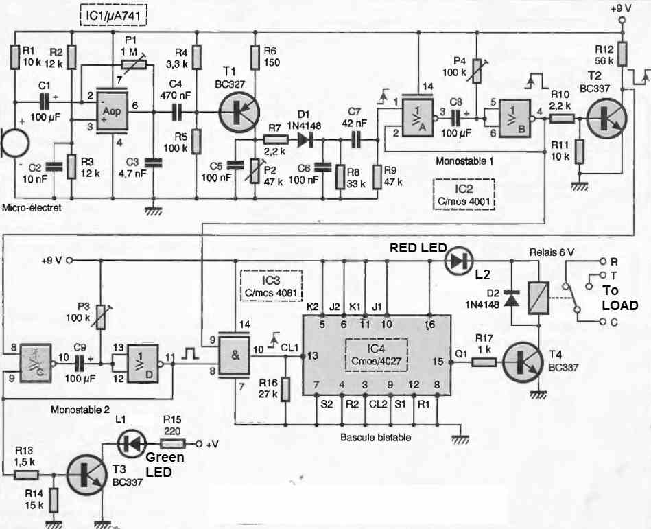
In order to achieve a unique IR remote control sets, the above design needs to be upgraded to a rather sophisticated tuned IR remote control system.
The diagram for the same may be studied below:
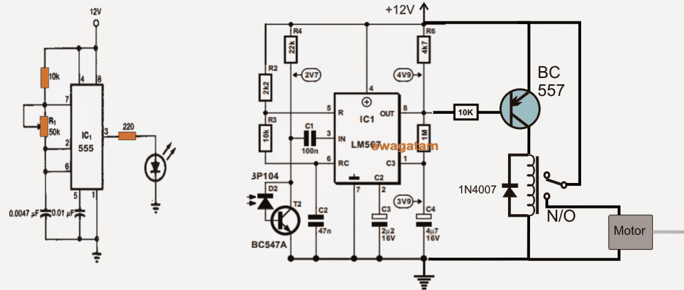
A detailed explanation of the concept may be read in the article titled Tuned infrared detector modules.
The article details the entire functioning of the relevant components used in the design and also regarding how to set up the modules in order to make them uniquely compatible with each other.


Questions & Answers
Hello,
Indeed your website is very helpful.
I have a request in the above mention circuit for fish tank feeder using tsop, My requirment is to continouly keep the relay in ON position, and for that is it possible to use a MOSFET for the purpose of switching, because I only need to switch the relay ON with remote, And the relay should not go OFF with the remote again.
Sir i made this circuit but it is not working the output of tsop1738 is continuously glowing the led and relay is on and off only when power cut off plzzz help me
Hi Amit, where did you connect the LED?
Please connect the LED in series with R3….
cut the link between the R3 and TSOP output pin.
connect LED cathode with TSOP output pin, and anode with R3, and now check the response
Hello,
My requirement for the circuit is like as mentioned above. I want the relay to in continously ON with using the remote to trigger it, and the relay to come back to OFF only when power supply is closed.
Hello,
if you want the relay to be permanently latched, once the remote is switched ON, then you can use the following modified design:
Thank u very much, the circuit wors as according to my requirement perfectly….
Thank u for your support….
Keep it up…
It’s my pleasure!
Response is same nothing happend
what response are you getting on the LED??? LED is ON or OFF
I remove the led and connect R3 to the output of tsop1738 but relay is on and off together when remote signal is giving to the tsop1738
1) disconnect R3 from TSOP output pin and check whether the relay is still ON or not if yes then the relay driver is not correctly assembled. If the relay OFF then chech TSOP. in the following manner:
2) put meter in V range. Connect red probe of the meter with output pin and black with negative supply. The meter should read full 5V as long as TSOP is not triggered….when triggered the meter should show almost zero volts….please check this and confirm
Hi, may I ask. Can I only build the first diagram of the circuit, which is with the remote control. Is it still can be functioning?
Hi, the first circuit will work but will work with any TV remote….so it cannot be restricted to a single unique remote
I’m using The Fish Feeder circuit but with another IR transmitter I build myself (not the tuned infrared detector) , this mean I didnot use the normal/available TV remote. Will it be functioning same as the TV remote? Or I need only to use a available TV remote?
only TV remote will work, or your other remote must be tuned with 38kHz frequency, then it will work
I mean, if I build an new IR transmitter remote circuit , wilFish Feeder detect the IR? will it be functioning like the TV remote ? I’m sorry but I’m confused.
You are welcome devendraji,
remote range cannot be increased above a certain limit, which could be around 5 to 10 meters….what is the present range for your remote?
That's great Devendra Ji…. commendable.
For faster response you can reduce the value of C2 only.
and for getting a delay OFF, you just have to remove R2 and replace it with a 100uF/25V capacitor, and increase the value of R4 to say may be 100K or more.
Dear Swagatam Majumdar
I am trying to make pooja led matrix (of 10-12) decorative low light led.
My requirement is that these LEDs should turn ON automatically in evening time as there will be darkness in room using LDR ….can just share with me the circuit diagram for the same.
regards
Dear Navneet, you can try the following concept for your requirement:
https://www.homemade-circuits.com/2011/12/simple-led-automatic-daynight-lamp.html
Hey Thanxs Swagatam for your prompt response.
Respectiv sir 3 problems come me for making circuit Low Battery Cut-off and Overload Protection Circuit
1. this circuit work for this battery 18650 li-ion 11.1v 6.6Ah battery ?
2. what is R1 = 0.6/Trip Current and how many watt?
3. what is setting of pre set is mark for this battery?
i use this battery pack in hero honda(super splender) biky for the self starting
pl help me
thankyou
Shuddhatam, no that circuit cannot be used for Li-ion batt, you can try any of the the following:
https://www.homemade-circuits.com/2012/07/make-6v-4ah-automatic-battery-charger.html
Pls sir give 2000watt pure sine wave inverter circuit pls
you can try this one:
https://www.homemade-circuits.com/2013/10/making-3kva-modified-sine-wave-inverter.html
sir i can also use this as door lock system right!!!!!!!!!!!
yes you can use the last circuit as a door lock…