A very simple low battery cut-off and overload protection circuit has been explained here.
The figure shows a very simple circuit set up which performs the function of an overload sensor and also as an under voltage detector.
In both the cases the circuit trips the relay for protecting the output under the above conditions.
How it Works
Transistor T1 is wired as a current sensor, where the resistor R1 forms the current to voltage converter.
The battery voltage has to pass through R1 before reaching the load at the output and therefore the current passing through it is proportionately transformed into voltage across it.
This voltage when crosses the 0.6V mark, triggers T1 into conduction.
The conduction of T1 grounds the base of T2 which gets immediately switched Off. The relay is also consequently switched OFF and so is the load.
T1 thus takes care of the over load and short circuit conditions.
Transistor T2 has been introduced for responding to T1's actions and also for detecting low voltage conditions.
When the battery voltage falls beyond a certain low voltage threshold, the base current of T2 becomes sufficiently low such that it's no longer able to hold the relay into conduction and switches it OFF and also the load.
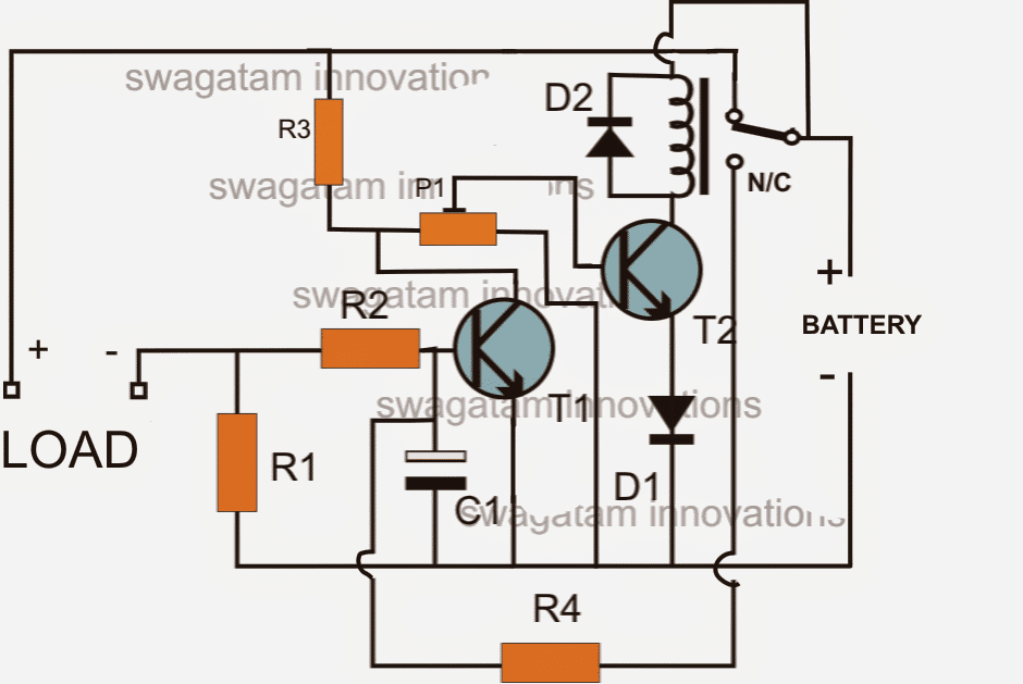
The"LOAD" terminals in the above diagram is supposed to be connected with the inverter +/- supply terminals.
This implies that the battery current from the right side has to pass through R1 before reaching the inverter, enabling the sensing circuit around R1 to sense a possible over current or overload situation.
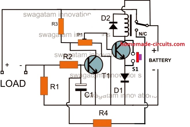
CORRECTION:
The above shown circuit will not initiate unless the relay is actuated manually through a push switch as shown below:
Parts List
- R1 = 0.6/Trip Current
- R2 = 100 Ohms,
- R3 =10k
- R4 = 100K,
- P1 = 10K PRESET
- C1 = 100uF/25V
- T1, T2 = BC547,
- Diodes = 1N4148
- Relay = As per the specs of the requirement.
Formulas and Calculations
Low Battery Cut-off Threshold
The low battery sensing is handled by R3 and P1 which forms a potential divider to set the base voltage of the relay driver transistor (T2). When the battery voltage drops below a set threshold the voltage at the base of T2 falls below Vbe (0.6V–0.7V) turning OFF the relay and disconnecting the load.
Formula for Threshold Voltage:
Vth = Vbat * (P1 / (P1 + R3))
- Where:
- Vth = Base threshold voltage (0.6V–0.7V)
- Vbat = Battery voltage
- P1 = Adjustable potentiometer resistance
- R3 = Fixed resistor
To calculate the battery voltage cut-off level:
Rearrange for Vbat:
Vbat = Vth * (P1 + R3) / P1
Overload/Overcurrent Sensing
Overcurrent protection is implemented using R1 which is placed between the base and emitter of transistor T1.
As the load current increases, the voltage drop across R1 rises. When the voltage across R1 reaches the Vbe of T1 (typically 0.6V–0.7V) T1 starts conducting and shunts the base current of T2 turning it OFF.
Formula for Overcurrent Trip Current:
Itrip = Vbe / R1
- Where:
- Itrip = Overcurrent trip current
- Vbe = Base-emitter threshold voltage of T1 (0.6V–0.7V)
- R1 = Resistor sensing the overcurrent
Base Current Limiting Resistor (R2)
Resistor R2 (optional) limits the base current for T1 to prevent excessive current through its base-emitter junction.
Formula for Base Resistor (if used):
R2 = (Vbat - Vbe) / Ib
- Where:
- Ib = Required base current for T1
- Vbat = Battery voltage
- Vbe = Base-emitter voltage of T1
For small signal transistors (e.g., BC547) Ib can be estimated as Iload / hFE where hFE is the DC current gain.
Inverter Overload Cut-OFF using Opamp
In the above paragraphs I have explained a very simple concept of inverter overload cut-off using only transistors.
However a cut off system using only transistors cannot be very accurate and sharp.
In order to get a precision inverter overload and short circuit cut off circuit the use of an opamp based design becomes imperative.
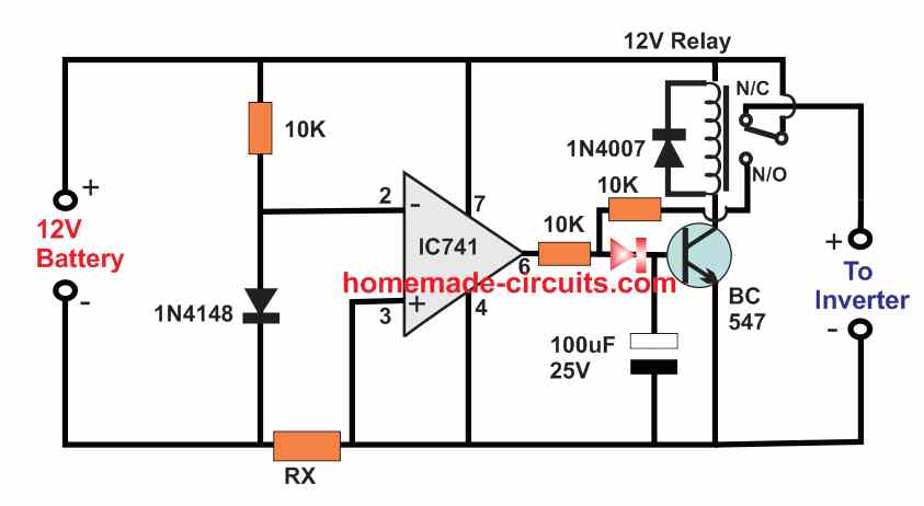
The following diagram shows a simple battery overload controller circuit using a single opamp 741 and a relay driver stage.
How it Works
The opamp is configured as a simple comparator circuit. he inverting input of the opamp is clamped at a fixed 0.6 V using a 1N4148 diode.
The non-inverting input of the op amp is connected with the negative line of the circuit through a over-current sensor resistor Rx.
Due to inverter overload or short circuit or over current conditions, a voltage drop develops across the resistor Rx which can exceed the 0.6V as per the calculated value of the RX, and cause the non-inverting input of the opamp potential to go higher then its inverter 0.6V potential.
This causes the op amp output to turn high activating the transistors and tripping the relay.
When power is first switched ON, and assuming the inverter is working normally without an overload, the voltage developed across RX is minimal, which keeps the pin3 potential of the opamp the opamp lower than the pin2 potential.
This allows the output of the opamp to be low ensuring that the transistor is switched OFF, and relay contacts stays at the N/C point.
Due to this the 12V is able to reach the inverter and operate it normally.
However, as soon as an overload or over current happens at the inverter side, a large amount of current passes through the RX resistor, causing a voltage drop to develop across pin3 of the IC.
When this voltage drop exceeds the 0.6V reference level of the pin2 of the IC, the output of the op amp goes high, causing the transistor to switch ON and trigger the relay.
The relay contacts now shift from N/C to N/O switching of power to the inverter and thereby averting the short circuit or overload conditions.
The N/O contact can be seen attached with the base of the relay driver transistor, which ensures that as soon as the an overload is detected the relay contact quickly latches the transistor, switching the power permanently off for the inverter.
The power can be restored only by disconnecting the 12 V battery input, but before that it must be ensured that the short circuit or the over load condition is appropriately removed from the inverter side.
Formulas and Calculations
Key Parameters
- RX: Current sensing resistor (ohms)
- Vref: Reference voltage at the inverting input (-) of IC741
- Itrip: Overcurrent trip current (amperes)
- Vdrop: Voltage drop across RX at trip current
Formulas
Voltage Drop Across RX:
Vdrop = Itrip * RX
- Where:
- Itrip = Overcurrent trip point (A)
- RX = Current sensing resistor (ohms)
Reference Voltage (Vref):
The voltage at the non-inverting input (+) of IC741 is set using a resistor divider or Zener diode (if used). For proper cutoff:
Vref ≈ Vdrop
Choosing RX (Sensing Resistor):
To calculate the value of RX for a given trip current:
RX = Vref / Itrip
- Where:
- Vref = Reference voltage (V)
- Itrip = Desired trip current (A)
Power Dissipation in RX:
The sensing resistor RX must handle the power dissipated during operation.
We will Use:
P = Itrip2 * RX
- Where:
- P = Power dissipation in RX (W)
Choose RX with a power rating higher than P for safe operation.
Example Calculation
Let’s assume:
Itrip = 10A (trip current)
Vref = 0.7V (reference voltage determined by the op-amp threshold)
Step 1: Calculate RX
RX = Vref / Itrip = 0.7 / 10 = 0.07 ohms
Step 2: Power Dissipation in RX
P = Itrip2 * RX = 102 * 0.07 = 7W
Choose a 0.07-ohm 10W resistor for RX to ensure safe operation.



Questions & Answers
pls sir can help with your email or link I can use and send an image to, I have this variable power supply circuit but I want you to help preview it if there’s any error. before implement the circuit or budget for it
Hi Okon, please upload it to your google drive and provide the “shared” link to me and I will check it out.
But please, for a power supply related article, please post it under a power supply related article…
sir how are you
I make construction inverter using sg3525 mosfet 4 ups transformer I tested output 473v AC
how decrease. voltage to 220
Abdulkareem,
It means, the transformer winding ratio is not suitable for 220V AC output, please change the secondary number of turns to get 250V, instead of such high value…
Good day sir, thank you for all your good works here. You have really helped so many especially me. More grease to your elbow.
I made an automatic low battery cut off circuit but it comes back on immediately the battery voltage increases above the cutoff level. Please help me with a circuit that will keep the Auto low battery cut off inactive until a preset button is pressed
You are welcome Hillary,
In your existing circuit please connect a high value resistor between 10k and 100k, between the N/C contact of the relay and the base of the relay driver transistor. Next, attach a push-button between emitter/collector of the transistor for the resetting the action.
I have done it but when an inductive load is connected to the inverter, the relay flickers
To control relay flickering, just connect a 220uF or a 470uF capacitor across the relay coil, make sure to connect it with correct polarity.
Düşük voltaj kesme devresinde role yerine paralel bağlı mosfetler kullanılabilir mi teşekkür ederim.
Good day sir, I made the battery low cut off and it works fine but then, when the circuit is activated at 10.5v, it automatically deactivates itself when the voltage goes back to 10.7v and this continues. So I want to ask if there is any other circuit to add to keep it activated until a reset button is pressed?
Hillary, which circuit are you using? It can be be latched using an SCR stage. Let me know which circuit are you using, I will try to modify it accordingly.
I am using Opamp circuit
The opamp circuit is not a low battery cut off circuit, it is an overcurrent/overload cut-off circuit, and it has a latching feature already.
how can I determine the Rx
RX = 0.7 / Maximum inverter current limit
how do i calculate the over load current of 1KVA inverter
Simply divide 1kva (1000 watts approx) with your battery voltage.
Good evening sir, please what value of shunt resistor can be used for 1000w inverter
Hi Hillary, Please provide the inverter operating voltage value.
The battery voltage is 12v
Hello, I have a question: Does the second circuit work as a short circuit protection at any point in the inverter?
Yes, it will work as a short circuit and overload cut off circuit.
Is it possible to use N-MOS instead of BC547 transistor?
Sorry, no, only NPN BJTs are recommended.
Please what is the RX resistor
RX = 0.7 / Max over load current
I have not yet work on the circuit but, I understand it very well sir. Sir! Is there a way that I use same transformer for both inverter and charger?
I wouldn’t recommend using a single transformer for both charging and the inverter as that can make the configuration too messy and difficult to optimize. Still, if you are willing to give it a try you can consider the following article:
https://www.homemade-circuits.com/single-transformer-inverterchargerchang/
Thank you so much sir, I love that circuit that have low voltage protection and charger, it will be very good for inverter. Thanks sir
Hello sir, if I use small transformer 220v to 12v for bridging diode to charger oscillation and use 30ahs relay for the charging output, will I have high current to charge battery?
The output current depends on the transformer current, so the transformer current must be according to the battery requirements.
You are welcome Michael, I hope you are able to build it successfully.
Okay sir, but how can I get accurate circuit for low voltage protection and over load protection
Michael, You can try the second design from the following article. Just make sure to make two changes. 1) Swap the pin2 and pin3 with each other. 2) Replace the “charging voltage input” with Inverter supply +/- inputs.
https://www.homemade-circuits.com/how-to-make-simple-low-battery-voltage/
Yes, the one I used was that op amp circuit but ic is lm358 which didn’t cut off voltage at 10.4v,
The op amp circuit is an overload cut off circuit, it is not a low voltage cut off circuit.
Thank you for the clarification, I have did it in project board but didn’t cut off when the battery is low at 10.4v
The transistor circuit cannot be very accurate, if you need more accuracy you may have to use an op amp circuit.
But what I mean before is, the ic lm358 have two output at pin 1 and pin 7, so it’s only one section I will use?
Yes that is correct, you will have to use only one op amp among the two!
Okay, thank you sir
Thanks for your quick response sir, but
the lm358 which you said I should how dual output, is it one of the output I need? Please help me with the circuit sir
Sorry, I cannot understand your question, what is the need of a dual output? the 741 circuit uses a relay for the cut off.
Can I use same circuit for 24v inverter
Yes, but replace the relay with a 24V relay and for the op amp circuit replace the 741 with LM358 op amp.