The proposed circuit is an oscillator circuit designed to generate a loud pistol like sound over a loudspeaker.
A pistol sound generator circuit presented here can be used as button operated starting sound during racing events or marathons, or simply to deter wild animals and thieves in remote areas. The concept could be also effectively applied in festivals such as Diwali for creating loud artificial bursting cracker sound (noise pollution is bad for health).

The circuit utilizes a discarded 60 watt loudspeaker for producing the banging loud pistol sound.
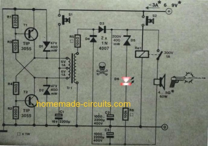
The main components that form the power oscillator circuit are T1 and T2 along with the mains transformer TR1.
S1 is used to initiate or power up the above circuit stage momentarily with a single push of the button.
The zener diodes provide the required protection to the transistors against inductive voltage spikes.
Since the oscillator circuit is a self oscillating circuit, its frequency is determined by the core material of the transformer, and also the magnitude of current drawn from the secondary of the transformer.
How the Circuit Operates
On pressing S1, the circuit begins oscillating at relatively high frequency which finally settles down to around 50 Hz as soon as C1 and C2 charges up.
The resistor R5 limits the current to acceptable limits, while the linked diodes D3, D4 form a voltage doubler configuration.
The voltage doubler stage is introduced to create many hundreds of voltage across the attached relay contacts.
The LED D6 lights up when C1, C2 are fully charged, and indicates S1 can be now released, and the second switch S2 is ready for the activation.
When the "fire" button S2 is pressed, the relay energizes, switching ON its contacts, which discharges an instantaneous high magnitudes of current and voltage over the loudspeaker coil, generating the required banging pistol sound. It must ensured that the speaker coil is adequately rated for handling this huge amount instantaneous blast of power.
The current consumption immediately after pressing S2 could be around 3 amps, which gradually comes down to around 0.5 amps as the C1 and C2 discharges to their nominal ranges.
The loudness or the "bang" volume of this pistol sound generator could be proportionately increased by raising the supply voltage to about 12V.
The complete circuit diagram of the proposed pistol sound simulator circuit could witnessed below:



Questions & Answers
Hi Swagatam,
I want to make this loud pistol sound circuit as you shown in the diagram, is that the latest diagram to work correctly.
Regards
Reza
Hi Reza, the circuit is not the latest diagram but the same one which was published originally.
However I strongly believe that the diagram is correct and would work as described.
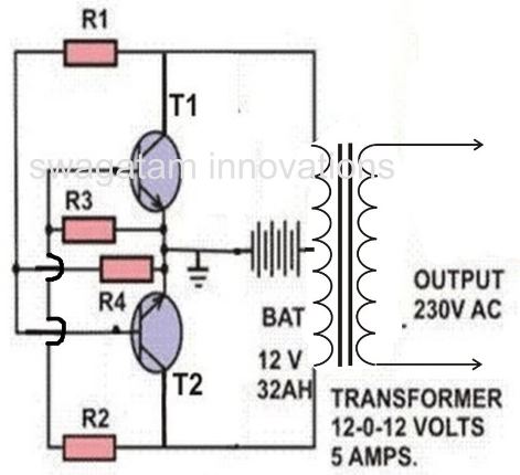
For further guarantee, you can replace the left side TIP3055 inverter section with the following inverter design which is a tested one:
The complete parts list given in the following article:
https://www.homemade-circuits.com/7-simple-inverter-circuits/
The secondary side of the pistol circuit can be as is.
Thank you Swagatam,
I appreciate your assistance.
Regards
You are most welcome Reza.
An SCR won’t work as a switch, the voltage starts out as a DC voltage and thanks to the Resonance between the Capacitor and Speaker it turns into a dampened sine wave, because of this a high voltage and high amperage relay must be used.
Thank you Clair, I appreciate your suggestion.
Swagatam, one idea to protect the speaker is to hook it up to your circuit in reverse, that way when the circuit is fired the speaker coil won’t separate from the magnet. Another idea is to put the speaker into a box (like a subwoofer box), that way the box will dampen the speaker protecting it.
Hi Swagatam,
I can’t get my oscillator cct to work. I was just wondering if there shouldn’t be a cap. between the T1 base T2 collector and the same for T2 & T1.
Your help will be much appreciated.
Regards
Jan
Hi Jan, capacitor is not required, the diagram is correct. Not sure why it isn’t working for you? You can perhaps try applying the first concept from the following article and replace it in your diagram
https://www.homemade-circuits.com/7-simple-inverter-circuits/
Thank you Swagatam for the advice. I am confident that I will find the problem. Fault finding makes things so much more interesting.
Regards
Jan
You are right Jan. Please keep up the good work!
Thank you Swagatam,
I appreciate your assistance.
Regards
Jan
You are welcome Jan!
Hi Swagatam,
I would like to change the circuit so that when S2 has completed its function S1 must automatically start its function. In other words I would like to replace S1 with a transistor or something similar which will sense when the S2 function has been completed, and then the transistor must switch ON to charge C1 & C2 and then OFF when the LED lights UP. This way the unit will be ready more quickly and only S1 needs to be activated when the LED comes on.
Do you think this is possible and if so please assist with a circuit change?
Your help will be much appreciated
Regards
Jan
Hi Jan, it may be possible in the following way: S1 can be replaced with a p channel MOSFET, source connected to positive line, drain to transformer center tap, and gate to ground via a 10K resistor. The LED can be replaced with an opto coupler with its transistor emitter connected to p channel mosfet gate via a 1N4007 diode. This opto emitter will also connect with the SCR gate via a 1K resistor. For slight delay the ScR gate can be connected with a 100uF capacitor across its gate and ground.
Hi Swagatam,
Which way should the diode go?
Regards
Jan
Hi Jan, the cathode will directly connect with the gate of p channel MOSFET
Than you Swagatam.
Much appreciated.
Regards
Jan
No Problem Jan!
Hi Swagatam,
I see one of your readers suggested that an SCR can be used instead of the relay. If this is possible I would prefer to use this method. Please give me the relevant information to make this modification to the cct.
Kind regards
Jan
Hi Jan, you can use a 1000V SCR in place of the relay contacts. You can eliminate C3 and diode D4 and connect the speaker ground with the common secondary ground. The gate of the SCR can be also connect to this ground via a 1K resistor, and the gate can be triggered by S2 via another series 1k resistor.
Thank you Swagatam,
Your advice is much appreciated.
Regards
Thank you for the info. Much appreciated.
Regards
Jan
My pleasure Jan..
You are welcome Jan!
Hi Swagatam,
Can I use 35uF 400v capacitors in the place of C2 & C3 and how will this affect the performance of the unit.
Regards
Jan
Hi jan, the output volume depends on C2, C3 value, lower values will give proportionately lower volume…35uF will produce very low volume.
Hi Swagatam,
I have finally completed building the cct. Had problems with getting parts due to the virus lockdown in our country. However I have managed to get it to work but unfortunately the speaker coil went open cct. The Jensen speaker is rated at 130W 4….8 ohms & 6.5 inches in dia. The discharge voltage to the speaker is 200VDC when C2 is charged up. Is it just my bad luck or did I do something wrong. I want to use a different speaker but am afraid I might damage that as well.
Please give me your opinion.
Regards
Jan
hi jan, did you include R5 (100 ohm) in the circuit. It is strange if the speaker blew with R5 in. It is definitely due to an over-voltage surge.
If the problem persists then you can eliminate D4 C3, and connect the speaker negative terminal with the C2 negative line, this will make the output 50% less and stop the speaker from burning
Hi Swagatam,
Yes I have included R5 (100R). I have modified the cct as per your suggestions previously which then excludes C3. If it is an over-voltage problem should D5 (200V Zener) not prevent this from happening? I definitely get 200V going to the speaker before activating S2.
Due to the lockdown I had to make do with components I had in my stock. So the cct is slightly different from yours. I will send you the cct when I have completed it.
Thank you very much for your reply
Regards
Jan
Hi jan, I am not sure about how much voltage a speaker is rated to handle? So I can’t figure out the actual reason. But you can reduce the output voltage by reducing the supply to the primary side, you can try 6V and check if that reduces the secondary to 100V
Loud Pistol sound simulator
some circuit improvements: use a relay with DC rated contacts, or use a SCR rated for 800 volts
Hi Swagatam,
Will you please give me the specifications of TR1.
Regards
Jan
Thank you Swagatam
My pleasure Jan!
Hi Jan, TR1 is a standard step down transformer 6-0-6/220V 1 amp
Exceptional site, thank you for sharing. One question tho, are D1, D2 and D5 zener diodes? I’m unfamiliar with that schematic symbol. Thank you in advance and I look forward to building this circuit.
Thank you, I’m glad you liked my site! Yes those are zener diodes, the symbol is typically used in elektor electronics magazine drawings. Wish you all the best for the project!