I am sure you might have often wondered how to accomplish the correct way of optimizing and calculating a modified square wave such that it produced almost an identical replication of a sine wave when used in an inverter application.
The calculations discussed in this article will help you to learn the technique through which a modified square wave circuit could be turned into sinewave equivalent. I have explained the procedures.
The first criterion to accomplish this is to match the RMS value of the modified square with the sinewave counterpart in a way that the result replicates the sinusoidal waveform as closely as possible.
What is RMS (Root Mean Square)
We know that the RMS of our home AC sinusoidal waveform voltage is determined by solving the following relationship:
Vpeak = √2 Vrms
Where Vpeak is the maximum limit or the peak limit of the sine waveform cycle, while the mean magnitude of the each cycle of the waveform is shown as the Vrms
The √2 in the formula helps us to find the mean value or the net value of an AC cycle which changes its voltage exponentially with time. Because the sinusoidal voltage value varies with time and is a function of time, it cannot be calculated by employing the basic average formula, instead we depend on the above formula.
Alternatively, AC RMS could be understood as an equivalent to that value of a direct current (DC) which produces an identical average power dissipation when connected across a resistive load.
OK, so now we know the formula for calculating the RMS of a sinewave cycle with reference to its peak voltage value.
This can be applied for evaluating the peak and the RMS for our home 50 Hz AC too. By solving this we get the RMS as 220V and peak as 310V for all 220V based mains AC systems.
Calculating Modified Square Wave RMS and Peak
Now let's see how this relationship could be applied in modified square wave inverters for setting up the right waveform cycles for a 220V system, which would correspond to a 220V AC sinusoidal equivalent.
We already know that the AC RMS is equivalent to the average power of a DC waveform. Which gives us this simple expression:
Vpeak = Vrms
But we also want the peak of the square wave to be at 310V, so it seems the above equation won't hold good and cannot be used for the purpose.
The criteria is to have 310V peak as well as an RMS or average value of 220V for each square wave cycle.
To solve this correctly we take the help of the ON/OFF time of the square waves, or the duty cycle percentage as I have explained below:
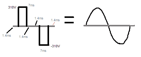
Each half cycle of a 50 Hz AC waveform has a time duration of 10 millisecond (ms).
A modified half wave cycle in its most crude form must look like as shown in the following image:
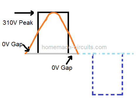
We can see that the each cycle begins with a zero or blank gap, then shoots up to 310V peak pulse and again ends with a 0V gap, the process then repeats for other half cycle.
In order to achieve the required 220V RMS we have to calculate and optimize the peak and the zero gap sections or the ON/OFF periods of the cycle such that the average value produces the required 220V.
The grey line represents the 50% period of the cycle, which is 10 ms.
Now we need to find out the proportions of the ON/OFF time which will produce an average of 220V. We do it in this way:
220 / 310 x 100 = 71 % approximately
This shows that the 310V peak in the above modified cycle should occupy 71% of the 10 ms period, while the two zero gaps should be 29% combined, or 14.5% each.
Therefore in a 10 ms length, the first zero section should be 1.4 ms, followed by the 310 V peak for 7 ms, and finally the last zero gap of another 1.4 ms.
Once this is accomplished we can expect the output from the inverter to produce a reasonably good replication of a sine waveform.
Despite of all these you may find that the output is not quite an ideal replication of the sine wave, because the discussed modified square wave is in its most basic form or a crude type. If we want the output to match the sine wave with maximum precision, then we have to go for an SPWM approach.
I hope the above discussion might have enlightened you regarding how to calculate and optimize a modified square for replicating sinewave output.
For practical verification, the readers can try applying the above technique to this simple modified inverter circuit.
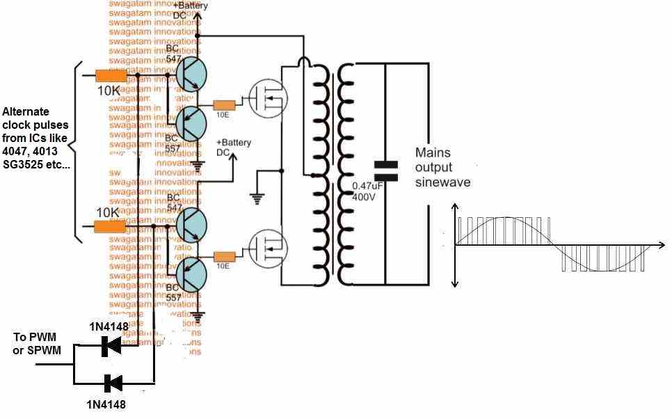
Here's another classic example of an optimized modified waveform for getting a good sine wave at the secondary of the transformer.

Questions & Answers
This may help others not wanting to do the math (apologies if it loses formatting when posted). Note that if you don’t care about phase offset, only half as many steps are required.
2-level Modified Sine
Step = 45 degrees
0, 0
45, Vpk
90, Vpk
135, 0
180, 0
225, -Vpk
270, -Vpk
315, 0
3-level Modified Sine
Step = 22.5 degrees
0.0, 0
22.5, sqrt(1 / 2) * Vpk
45.0, sqrt(1 / 2) * Vpk
67.5, Vpk
90.0, Vpk
112.5, sqrt(1 / 2) * Vpk
135.0, sqrt(1 / 2) * Vpk
157.5, 0
180.0, 0
202.5, -sqrt(1 / 2) * Vpk
225.0, -sqrt(1 / 2) * Vpk
247.5, -Vpk
270.0, -Vpk
292.5, -sqrt(1 / 2) * Vpk
315.0, -sqrt(1 / 2) * Vpk
337.5, 0
5-level Modified Sine
Step = 15 degrees
0, 0
15, sqrt(1 / 3) * Vpk
30, sqrt(1 / 3) * Vpk
45, sqrt(2 / 3) * Vpk
60, sqrt(2 / 3) * Vpk
75, Vpk
90, Vpk
105, sqrt(2 / 3) * Vpk
120, sqrt(2 / 3) * Vpk
135, sqrt(1 / 3) * Vpk
150, sqrt(1 / 3) * Vpk
165, 0
180, 0
195, -sqrt(1 / 3) * Vpk
210, -sqrt(1 / 3) * Vpk
225, -sqrt(2 / 3) * Vpk
240, -sqrt(2 / 3) * Vpk
255, -Vpk
270, -Vpk
285, -sqrt(2 / 3) * Vpk
300, -sqrt(2 / 3) * Vpk
315, -sqrt(1 / 3) * Vpk
330, -sqrt(1 / 3) * Vpk
345, 0
If Vpeak is constant for 180 degrees (full interval),
Vrms = sqrt(Vpeak^2 * 180 / 180) = Vpeak
If Vpeak drops to 0 for 90 degrees (half the interval),
Vrms = sqrt(Vpeak^2 * 90 / 180) = Vpeak / sqrt(2)
So it isnt 29% interval reduction but 50% for equivalent Vrms.
gostei muito dos projetos exelentes
Que bom que você gostou deles
great work and explanation. thumb up!.
I want to ask how can I incorporate this into an inverter circuit. I mean to get desired results from MOSFET
Thank you holawaleh,
you can implement this quite effectively using an IC 555 and IC 4017 based inverter circuit. Since IC 4017 has 10 outputs, we can optimize 5 outputs for one channel and other 5 for the other channel in a center tap based inverter circuit
From these 5 outputs skip the 1st and the 5th (keep them unconnected), and combine the middle 3 pins through diodes and join the diode ends with the gate of the mosfet. Do this for both the channels. This will quite effectively allow you to accomplish a 310V peak and a 220V RMS sine wave at the transformer output.