As the name suggests, this device generates electronic sound, resembling human laughter.

BASIC DESIGN
To enable the circuit start the proposed operations, it must have a fundamental sound input or frequency for processing.
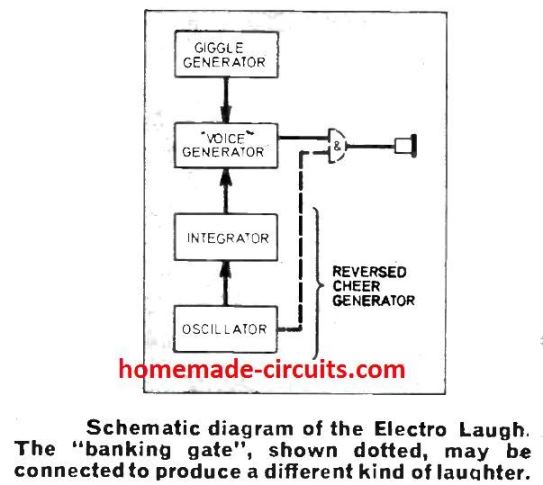
This basic frequency is established through a simple oscillator operating at 1 kHz frequency. The next, requirement would be to process this basic frequency through additional stages so that it imitates a human laughter sound. Please see the block diagram below for the details:
Due to the fact that, there's no "particular laughing sound" that may be followed in our electronic imitation circuit, hence the decision had to be an overall replica of most commonly heard laughter types.
Upon investigation, it was found that the majority of laughter sound felt like beginning at a specific stage within the sound range, which drops pretty fast to a frequency level approximately an octave lower. It can be compared to a soccer cheering heard in the reverse tone.
This sort of noise identified as a glissando) may be easily generated through the output voltage that comes from a basic integrator powered by a low frequency square wave oscillator which alters the voice generator frequency.
Also, the circuit must have the ability to make and break this characteristic in quite short bursts.
Each of these burst is supposed to cause a kind of warbling impact on the existing frequency with a declining frequency. To accomplish this an extra oscillator, named as the "giggle generator" has been included.
This stage continuously toggles the frequency of the basic "voice generator" from a single set position within the voice range to a new one. Once powered, the voltage from the integrator part of the "reversed cheer" generator is going to increase and decrease, creating a proportionate increase and decrease in the amplitude of the tone of voice.
However in case desired, the rising section of the tone may be prevented through a blanking gate network, as indicated in the above schematic block diagram.
How the Circuit Works
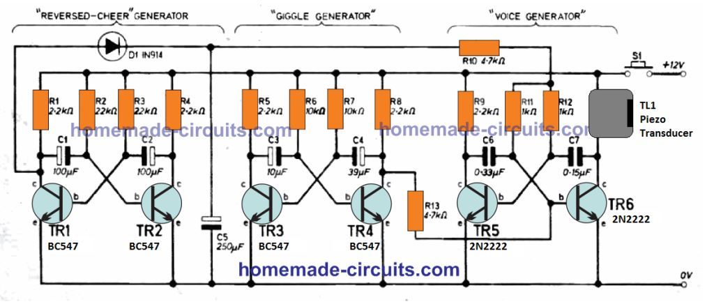
The Electronic Laugh simulator circuit works with three square wave astable oscillators. Except the part values of the individual astables which are adjusted with specific frequencies, the operating principle is simply identical. However the flip-flop (multivibrator) has a different functioning and I have explained more about it in the below given description.
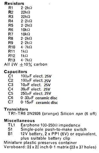
Parts List
Please refer to the oscillator section in the "reversed cheer" generator stage of the above figure. As soon as power is switched ON, we could imagine TR1 switching ON and causing C1 junction at TR1 collector to be pulled at almost ground level.
Because of this, C1 that may have by now charged to nearly + supply potential, starts to discharge. During this period C2 swiftly charges up to the supply potential. When C1 has discharged to around 0.6V (i.e., the Vbe of TR2) TR2 begin to turn ON. Because of the feedback between the two sides of the circuit, a fast changeover takes place causing TR2 to turn ON intensely and TR1 to switch OFF.
This operation then goes on and on repeatedly with C2 discharging and C1 charging, until the time TR1 activates again and TR2 gets deactivated. This carries on infinitely, or until the circuit is powered off.
The C1, C2 discharge rates are primarily established with the values of R2 and R3, while the average time constant (1.4CR) decides the operating frequency. The charging intervals for C1 and C2 are dependent around the values of R1 and R4, that normally tend to be quite small and therefore may be simply ignored.
During the time when TR1 is cut off, the positive potential from its collector is allowed to freely charge the capacitor C5. This causes the voltage across C5 to rise towards the supply level while TR1 continues to be in the non-conducting state.
However, when TR1 gets the opportunity to turn ON, it causes D1 to get reverse-biased. Due to this C5 slowly discharges via R10, R11, R12, and the bases of TR5 and TR6.
This process in which C5 is charged and a discharged slowly, results in a constant variation of the voltage levels where C6 and C7 start discharging in the voice generator stage.
This impacts the average time constant of the frequency and consequently the output signal results also get affected.
This implies that the increase in the charging voltage across C5 does not cause a rising effect on the pitch of the signal.
The purpose of the "giggle generator" output is to momentarily force a quick switching of frequency of the "voice generator" while the "reversed cheer" is in action. This is successfully implemented by linking the collector of TR4, to the base of TR6 through R13.
BLANKING GATE
If you are interested to get a different kind of laughter simulation, this could be obtained by integrating a blanking gate network as shown in the above figure.
When this circuit stage is introduced, the voice generator functioning gets inhibited due to TR6 base being grounded, whenever TR7 is switched on. Meaning this allows, only the decreasing (discharging) action of the integrator on the "reversed -cheer" generator to perform at the output of the circuit.


Questions & Answers
Swagatam, I’ve discovered that if an Electronic Circuit was designed to work with Germanium Transistors it will only work with Germanium Transistors. One example of a circuit is titled “Electronic Do, Re, MI” printed in the October 1961 Popular Electronics Magazine.
Thanks Clair for the information, however the only difference between a silicon bjt and a germanium bjt is their minimum base switching voltage, for a silicon bjt it is 0.7V and for a germanium it is around 0.2V..so I think the parameter is not too critical and the biasing can be simply adjusted with resistors.
Swagatam, what is the magazine and the date that this circuit originally came from? I tried this circuit on the afternoon of 02-21-2024 but because I forgot R13 I couldn’t get the circuit to work. I used a 10uf tantalum capacitor for C3. Also for C4 I paralleled a 30uF (31.1uF) and a 6.8UF (7.7uF) tantalum capacitor, also I didn’t have a 100 to 250 ohm speaker so I used the Class B amplifier circuit from “Best IC 4060 Circuits, Simple Timer With Alarm” I paralleled two 1/4 W 470 ohm resistors and I hooked the speaker to the emitter to ground.
Hi Clair,
The above circuit was submitted by an external author so I am not sure about the actual source of the content. As you can see the design is composed of 3 transistor astable stages, which are very basic, so if you configure these astables separately and test them separately and then hook them up as shown then I think it will be easier to get the circuit working quickly. However, yes, all the components will need to be as suggested in the diagram…for the speaker you can initially try any headphones, rest nothing is too critical about the circuit…I hope you will be able to succeed with this project soon.