The following post illustrates a simple light toggled/operated remote control circuit, which can be activated by an ordinary flashlight or more effectively through a laser beam unit (key chain type).
The circuit idea may be understood with the below mentioned points:
How the Circuit Functions
Transistor T3 along with the associated parts and the LDR forms a simple light sensor stage.
The LDR is connected across the base of the transistor and the negative supply such that when light falls over the LDR, BC557 receives the required base bias and conducts.
When BC557 conducts, the high potential at pin 14 of IC1 is pulled to logic high, and the output of the IC changes state activating or deactivating the relay.
The above condition persists until the LDR is illuminated again with a flashlight or with a laser beam.
The above operation alternately toggles the output ON and OFF providing the required toggling actions to the connected load.
The LDR must be covered inside an opaque pipe, about an inch long so that the ambient light stays obstructed from the LDR.
The angle of the pipe should be kept in a such a way that it facilitates easy focusing of the light beam toward the LDR.
C6 ensures that the system does not respond to accidental spurious light beams in case it finds its way inside the pipe, and over the LDR.
Video Test Proof
Circuit Diagram
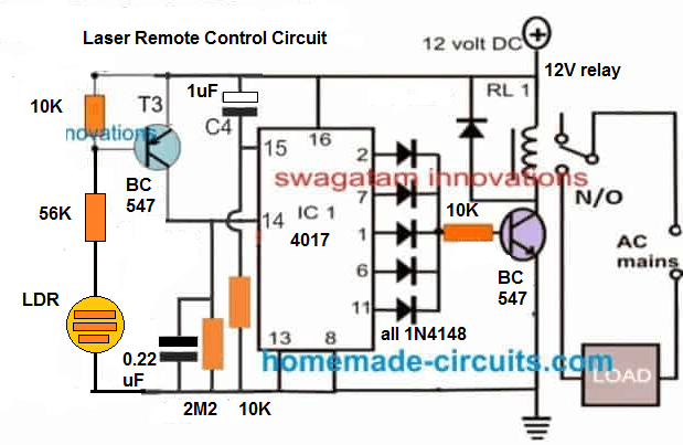
NOTE: T3 IS INCORRECTLY SHOWN AS BC547, IT IS ACTUALLY A BC557 PNP TRANSISTOR.
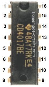
Parts List for the above light operated remote control circuit
R3,R4,R5,R6,R7 = 2K2
T1 = BC547,
T2 = BC557
IC1 = 4017
IC2 = 7812
ALL DIODES = 1N4007
C6,C7 = 10uF/25V
C8 = 1000uF/25V
C10 = 0.1uF



Questions & Answers
Hi sir, its wonderfull project. I want to make this project but sir there is confussion diagram and parts list both are diffrent, plz provide me full diagram, and also can we use 47k instead of 56k?
Thank you Ghulam,
You can surely try this project. It would suggest you to follow the parts which are indicated in the circuit diagram.
I will correct the parts list soon so that it also includes the same parts which are shown in the diagram.
The resistor values are not critical at all, any nearby values will work without any issues.
Sir i tried and its working, thank you…sir i need some modification if its possible plz, i want to add touch module(ttp223) also in this circut, plz guide me how to add plz
Hi Ghulam,
where do you want to connect the touch switch, I am asking this because the above circuit is a light operated switch.
For touch operated switch you can refer to the following article:
https://www.homemade-circuits.com/ttp223-capacitive-touch-module-explained/
Sir i want to use in this same circut, like i want both option to operate load, from laser also if i want i can use or from touch also……
Hi Ghulam, you can try the following modified design and check whether it works or not:
The touch pad is nothing but any 1 inch stripped wire.
Yes sir its working, but if i fix this in the box then may be not work, i tried with ttp223 touch module in same way, i used 5 volt relay, so i give 5 volt supply, i used with base 1 k resister, its wotks but there is one issue, once we pressed touch load is on, and again touch load not off but module off, again we touch load on. May be due to resister value, or any other issue, plz guide me, i want to use ttp223 module for proper work plz
Ghulam, you must first check and confirm the TTP223 working separately using an LED.
It must be configured like a flip flop.
Please read this article and check how the module must be configured as a flip-flop
https://www.homemade-circuits.com/ttp223-capacitive-touch-module-explained/
Shorting the pads B converts the TTP223 module output into a flip-flop toggle mode.
Yes sir B pads already short, and sepreatly i checked its working.
Sorry Ghulam, the flip flip mode is not required because the 4017 is already working like a flip flop…
So the ttp223 just needs to be a touch to ON and then off mode…B pad does not need to be shorted…
Yes its working without shorting B pad, now one more i need your support, i want to run this transformless power supply, input voltage 5 volt, because i used 6 volt relay, and touch module….plz provide me diagram for transformerless power supply for long time plz
Transformerless circuit will make the circuit dangerous to touch because the whole circuit will be floating with 220V AC.
Instead you can power it through a mobile charger output voltage.
Will this work using a green laser?
It will work with green laser also.
Hello! I have no background in circuits but I have a question about the laser beam light activated circuit. Would I be able to use a circuit like this to activate a large electronic, such as a computer monitor, to turn on?
Hello, you can connect any desired load by wiring it across the relay contacts.
Ref. Laser Remote Circuit. Hi, Years ago I found a circuit, (searched, can’t find it) that would toggle via a laser only, not a flashlight or ambient light such as in your circuit. As I recall it utilized two LDR’s mounted close together. If a laser beam were to hit either one but not the other, it would toggle. A wider beam such as a flashlight would not because the beam would illuminate both LDR’s equally.
Can you modify your circuit to do that! It would be more secure this way and still work well with a pocket laser. I never miss your publications and am amazed how you keep up with so many questions and designs. You do a great service to all of us. Thanks for that. Jack
Got your message. Thanks!
Hi, it can be easily achieved through a single ex-OR gate IC such as 7486. The IC 555 may not be required fr that, I will try to update the idea soon
Good
Hi Sir Swagatam, I need a circuit similar to the circuit above but I will use the LED of mobile phone as light source so I can turn ON and OFF the load using mobile phone. The load will be activated only after two rings of the phone, after 1st ring the device will wait for the 2nd ring within 2 or 3 minutes or else the 1st ring will be discarded to avoid unintended triggering of the load. If possible the supply of the 4017 IC is 3.7V so I can connect it to mobile phone battery to preserve the output state in case of power interruption, the relay section can be connected separately to 12V so it will not drain the phone battery.
Thank you Sir in advance and more power to you!
Hi Dondon, I'll try to design the required circuit, and let you know once it gets published
Hi How to make a simple ir sensor circuit
Hi, I have built many of your amazing circuits but the laser circuit does not seem to work, there are no changes when the laser is aimed to the LDR. I have built the circuit twice and still no results. I require a circuit that can work like and on off light switch but controlled by a laser.
Thank you.
still its not working
Hi, remove R3 and then check. When light falls on the LDR, pin14 potential should become zero, and as soon as the light is switched off, pin14 should become high in potential and consequently result in switching of the output.
0-220 is the primary, 0-12 is the secondary of the transformer.
you can use one of the taps (0-12) from your 12-0-12 trafo
relay coil voltage should be equal to the transformer voltage value, and the contacts rated to handle the load current.