In this post I have explained a simple ultrasonic weapon circuit also called USW, using very ordinary parts such as IC 555 and a few other passive components to generate the required ultrasonic ear piercing sound.
Controlling Crime with USW
With rising crime in today's society, especially against woman, carrying some sort of effective weapon has become quite imperative.
However keeping weapons like a hand gun can be too risky and dangerous as it can lead to deaths or severe injuries and might instigate legal interventions.
A great option which can be as effective in such cases yet won't cross dangerous limits can be in the form of a USW or an ultrasonic weapon.
What is a USW
An USW is a device or an electronic circuit designed for generating ear piercing, unpleasant frequencies that may be capable of causing intensely disturbing or painful affects for the assailant. when targeted toward the human attacker or an animal.
This sonic devastator will generally work with amplified frequencies of around 10 to 15kHz with a sweeping effect, resembling the sound created when we scratch our nail on a bar of chalk or limestone (amplify it 50 times).
Such USW devices are already available in the market but making one at home can be real fun and also useful.
A simple version can be witnessed below which incorporates a couple IC 555s for the intended actions. The proposed ultrasonic weapon circuit may be understood as follows:
Basically both the ICs are configured as astable multivibrators, but the one at the left is used as a slow rising and falling ramp generator or triangle wave generator.
Circuit Operation
The IC 555 at the right is wired up as a high frequency generator determined by the 1.5k resistor, P2 and the 0.01uF capacitor.
The slow rising/falling ramp from across the 1uF capacitor of left IC555 is applied to the control input pin#5 of the right hand side astable IC555 stage.
The above integration results in an high frequency sweeping voltage at pin#3 of the right hand IC which is fed to the transistor current amplifier stage consisting of the power transistor D40D5 or any other similar NPN equivalent.
This amplified current is further fed to a couple of inductors which transform the high current into high voltage frequency suitable for driving high impact piezo transducers or buzzer elements.
For the two parallel inductors, here we incorporate the primaries of an ordinary radio audio output driver transformers and the series inductor can be any type having the value of around 1000uH.
S4 is the push to ON switch used for triggering the circuit into operation.
S1 is for selecting fast or slow sweep effect option, while S3 is the frequency selector switch, to be selected for fixing the optimal frequency range. P2 sets the final frequency to be delivered across the output.
Adjusting the Frequency Sweep
P1 is for correcting the desired sweep speeds.
The whole circuit operates at 18V, lower voltages upto 12V can also be tried with good results.
A battery pack made from chargeable Ni-Cd cells suits good enough for this ultrasonic weapon application.
The whole unit must be installed inside a plastic enclosure made by fabricating plastic pipes in such away that it resembles a pistol kind of appearance with S4 positioned at the trigger button position.
The piezo must be assembled inside a funnel mouth, and whole assembly to be fixed at the tip of the above fabricated gun barrel.
Circuit Diagram of Sonic Devastator
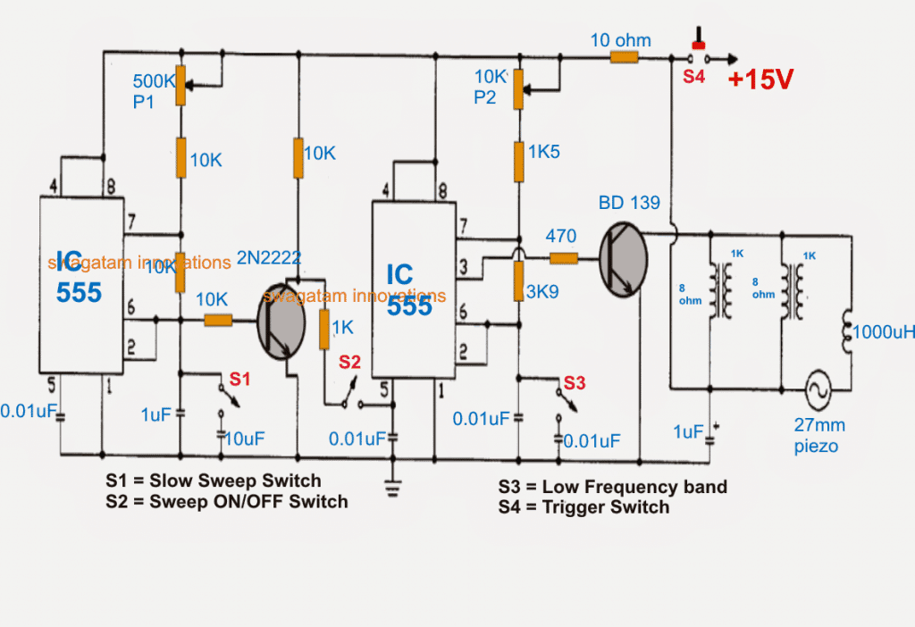
A deeper investigation shows that the sweeping feature of the left side IC 555 via the 2N2222 transistor can be achieved only when the 2N2222 is configured like an emitter follower, as shown in the following modified diagram.
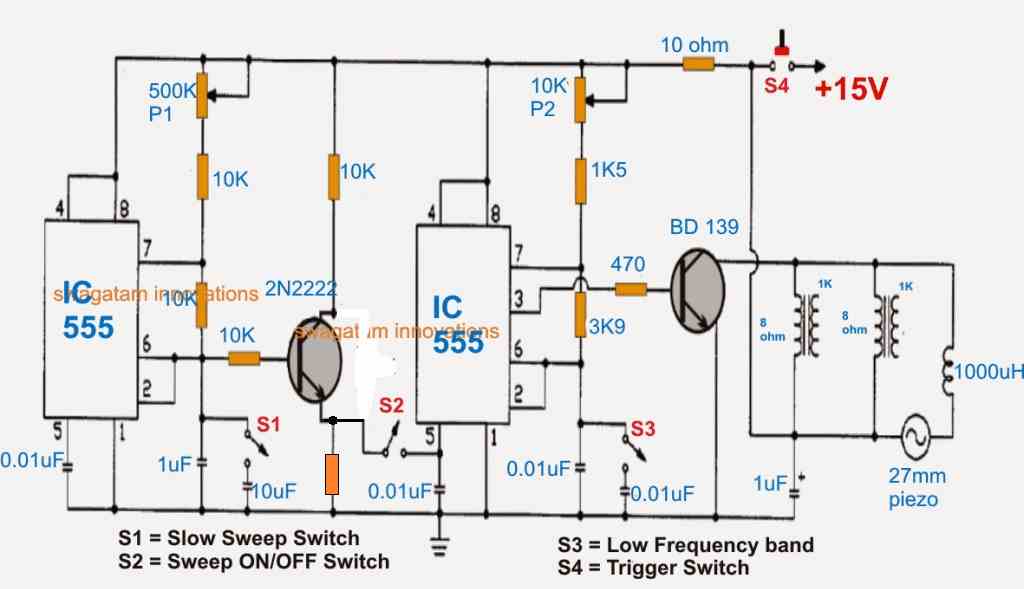
The triangle waves from pin6/2 of the left side will generate a modulating triangle wave, which will amplified by the 2N2222 to feed the pin#5 of the right side 555 and this will generate the intended sharp sweeping ON OFF switching sound on the piezo transducer.
Parts List
Resistors 1/4 watt 5% CFR
- 10k = 4
- 10 Ohm = 1
- 1k5 = 1
- 3.9k = 1
- 470 ohms = 1
- 1k = 1 (at the emitter of 2N2222)
- Preset 500k = 1
- Preset 10k = 1
Capacitors
- 0.01uF = 4 (ceramic disc)
- 1uF/25V = 2 (electrolytic)
- 10uF/25V = 1 (electrolytic)
Transistors
- 2N2222 = 1
- BD139 or TIP31 = 1
IC 555 = 2
Audio Output Transformer = 1 or 2
Piezo Transducer = 1 (Assembled inside plastic enclosure)
Inductor = 1000uH
Note: The audio transformers can be completely eliminated if the piezo and the inductor are configured in parallel, between the collector of BD139 and the positive line.
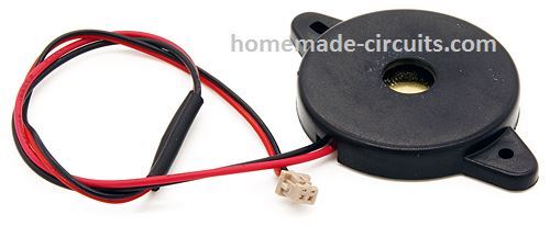
The inductor can be any buzzer coil, and the piezo can be a 27mm piezo assembled inside a plastic enclosure.
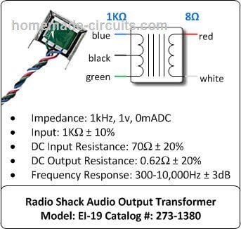
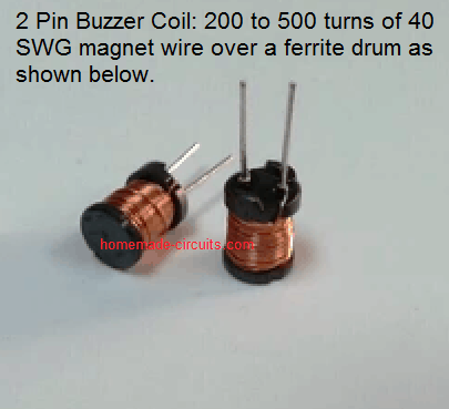
Transducer Driver Coil Details
How to Make a Long Distance USW
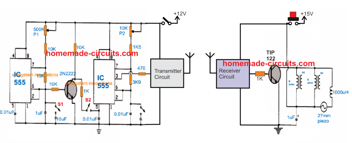
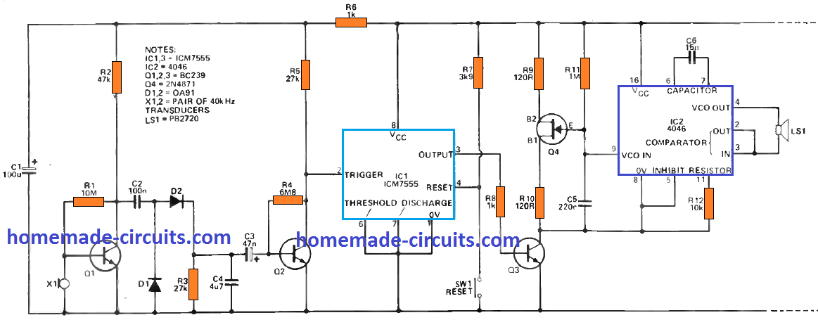
The above design could be effectively used for remote long distance control by configuring it with a pair of RF FM transmitter and receiver circuit as shown below:




Questions & Answers
I want it so loud to scare away the UAP flying over my house daily. I want to send the aliens back to outer space. Help me pierce the aliens ears. Thank you.
I want a finish product but not the spare parts, as I don’t have the experience in assembing them, I want a finish producct (complet one).
Your work here is very much appreciated. I am wondering if someone with no education or experience in building a circuit board is able to complete one of your listed projects. I know BBROYGBV GW and how a circuit board functions, but no knowledge of what components do or how to wire them properly. And I am only assuming I would know how to follow a schematic. I have soldered a bit and have a fair amount of interest.
Thank for kind feedback and comment!
If you are a newcomer then I would suggest you to start with small circuits, and learn how to build and test them successfully.
As you succeed with these projects you can attempt for relatively bigger projects.
In the course if you have any issues with the circuits, you can always feel free to comment under the relevant posts and get my help to solve your queries.
I REALLY NEED SOME HELP. NOT BEING FUNNY BUT MY NEIGHBORS ARE USING SOME KIND OF INFRASONIC SOUND AGAINST ME. I AM IN PAIN ON A DAILY BASIS. RECENTLY THEY ALMOST CAUSED ME TO HAVE A HEART ATTACK. SEVERE PAIN AND VIBRATIONS IN MY CHEST. I WOKE UP TO LEVELS OF 3,9HZ TO 6.64HZ. IS THEIR ANYONE OUT THERE THAT CAN HELP ME. PLEASE DO NOT RESPOND IF YOU NEED TO BE FUNNY OR RUDE OR DISRESPECTFUL. I AM 72 YEARS OLD AND NOT IN MOOD FOR FOOLISHNESS. I HAVE SEVERE EAR PAIN AND PRESSURE AND POPPING IN MY EARS AS WELL AS OTHER SYMPTOMS IF YOU NEED TO KNOW. I WANT TO DEVELOPE A DEVICE TO DO TO THEM WHAT THEY ARE DOING TO ME.
It is difficult to write what you are experiencing, I imagine. There are real world scenarios that people experience that others may view with some skeptisism. I wish I had the knowledge to help you with your concern/question and hope you have received assistance and answers from others. It is these types of ‘invisible’ harm and the difficulty establishing evidence that makes this such a difficult problem to relieve.
Are there any tests to identify a sonic weapon or a sound device? Kind of how there are laser detectors
Hello. I really need your help. Ive complained to authorities about low, loud flyovers over our secluded home, and now there are weird sounds that resemble something hitting the house. Plus a jarring dull thud felt thru the floor. We have security cams, but this stuff does not record. Im researching and would like to know if you can help us figure this out?
Thnx in advance.
Sue and Steve Miller
Do you feel comfortable giving a rough location of where without actually giving your address.
How loud are the flyovers? Aircraft or quadcopter?
Hello Swagatam,
I fired up the circuit for the 1st time using 12v DC power supply, the piezo started to produce sound after switching on S1, (S2 & S3 were open circuit) then realized I should have attached a heat sink to BD139, after noticing it was getting super hot, tried again, but to late, I’ve managed to cook BD139 and also noticed both transformers were both getting quite warm, I check the circuit of errors, have i missed something.
Appreciate your advise.
Cheers
Hello David,
It seems your transformer impedance is not matching the 12V supply. I would recommend using 5V supply initially and check if that helps to keep the transistor cool.

The best way to ensure that the transistor and the coil work correctly would be to use a 2-pin piezo buzzer coil instead of a transformer. This coil can be connected between the transistor collector and the positive line. The piezo transducer can be simply hooked up parallel with this buzzer coil for an enhanced high audio output.
An example image of the buzzer coil can be witnessed in the below link:
These can be easily purchased from any online retailer:
https://www.google.com/search?q=buy%20buzzer%20coil%20inductor&tbm=isch&hl=en&tbs=rimg:CdypiSokoTLSYR_1n5Pb8wVqn8AEAsgIOCgIIABAAKAE6BAgBEAE&sa=X&ved=0CBsQuIIBahcKEwigzYzo-Lb4AhUAAAAAHQAAAAAQCA&biw=1583&bih=757
Hi Swagatam,
I can only source 63V Electrolytic Capacitors will that caused problem.
Cheers
Hi David, the criterion is, voltage rating must at least 1.5 times the supply voltage, if it is higher than this then no issues at all, but it should not be less. So 63 V is great no problems.
Hello Swagatam,
Thank you 🙂
Hi Swagatam,
I’m new to electronics any chance you can send a components list.
I happen to notice one of the 1uf capacitors on the right of the circuit is electrolytic is that correct.
Cheers
Hi David, I have added the required information in the above article, you can check it out. Yes all the 1uF and the 10uF are electrolytic
Hi Swagatam,
Redarding, Circuit Diagram of Sonic Devastator.
Do you have an updated circuit that will resolve issue with pin 6/2 as commented a previous post.
Also can you please indicate the effectiveness of Sonic Devastator.
Hi David, According to me the 2N2222 transistor must be configured in the following manner.
Alternatively the existing diagram can be used with the base of the 2N2222 connected to pin3 of the left IC 555 instead of the pin6/2.
If the transformers at the output are correctly selected and connected with a piezo transducer then the circuit can be very effective in creating an ear piercing sweeping sound.
Thank you Swagatam,
hi folks,
While I suspect few dentists would consider this an Ultrasonic Weapon but I was looking at ultrasonic dental scalers and wondered how they might be controlled in terms of power.
The basic principle is that of an US generator 28khz or so being generated in a hand piece that controls a jet of water (which essentially acts as the transmission medium between the hand piece and the dental plaque being removed.
I suspect that the power setting is simply a pulse width modulator control to alter the duty cycle of the 28khz signal.
Two questions. The first would be how to best implement this recognizing the limitations of frequency/current draw and voltage and second, could this be easily applied to one of the cheap Chinese 100watt driver boards.
Thanks Guys!
Take care,
Doug
Hi Swagatam,
I’m no expert in electronics. But I purchased a home and have been experiencing, what was refered to me as sonic bullets. It causes the muscle to jerk. Its effective in keeping you awake. Also high pressure to my sides and a high pitch ringing in my ears. I only experience this at home. When I’m away at work or a family members house or friend I do not have this problem. If possible, can you tell me what device would cause this and how to block it. I’m not very aggressive and only wish to protect myself. I would like to move, but cant afford to at this time. Any help would be very appreciated.
Joe
Hi Joe, I am sorry to hear your problem, however I do not have much idea regarding sonic bullets or how to eliminate them. I have an article on how to detect RF signals in a house, I am not sure if this can be helpful or not, but you can try building it and check if it helps to detect the source of the pulses.
Anti Spy RF Detector Circuit – Wireless Bug Detector
Sir,
P L E A S E .. Advise which transmitter and receiver I should purchase for your LONG RANGE USW project, I have all the rest of the components except he TRANSMITTER and RECEIVER Modules.
Your earnest attention and reply would be highly appreciated thanks
Christian
Christian, sorry I don’t sell these units from this website, I can only help making the circuits….
Hi Swagatam,
I need your assistance please. I have built your Ultrasonic weapon, however I have problems.
The left 555 PIN 2 & 6 feeding the base of 2N2222 does not switch the transistor. Without the base connected I get a very slow freq. alternating between 2 & 3V from the IC. When I connect the base the base voltage falls to zero. The transistor is not faulty as I have manually switched it. When I connect the base to IC PIN 3 which output a 1 – 4.5Hz square wave signal then the transistor will switch on & off as per the base signal. On the R/H 555 PIN 3 the frequency is 11-17 kHz & switches on/off as per the timing on L/H IC PIN 3 signal. I do get sound out of the Piezo, but it is really nothing more than a beeper. The volume from the Piezo is rather weak but I can adjust the slow freq. on P1 & the high freq. on P2. I think the weak volume could be due to the speaker transformers & Inductor. I have use equivalents but their values are not correct. I have ordered the correct parts. Should have it soon and hopefully this will correct the volume problem.
The supply voltage is 15VDC
I have swapped the 555 numerous times with other IC’s, but symptoms are identical.
I have tried different values of resistors, but no luck.
I have checked the CCT and Continuity between components & everything seems to be OK.
Your assistance will be much appreciated.
Regards
Jan
Hi Jan, I had referred this diagram from another site, and it seems the left side astable is incorrectly shown with pin6/2 connected with the base of 2N2222. It should be basically a replication of the right side astable design. So please use pin3 of the IC to drive the 2N2222.
The piezo will need a special inductor and the piezo will need to be mounted or fixed over a specially design plastic enclosure, for generating a loud noise. Without these arrangements the piezo will be very weak with its output.
Thank you Swagatam,
Will you please give me the specs for the special inductor.
Regards
Jan
The coil can be any small ferrite rod based coil with 200 to 600 turns on it. Or you can also get ready made “buzzer coils”
Its working thanks for circuit but when i turning on 10ohm already burned and still working with burning 10ohm what can i do about it?
And sound a bit weak what can i do?
Thanks have a good day swagatam
Trishopta, please use a 10 Ohm 3 watt or 5 watt wirewound resistor, 1/4 watt will burn quickly.
Do you have counterpart here in the Philippines where I can buy the kit? Thank you
Sorry I do not have anybody in Philippines who can provide you the kits.
kindly provide model or supplier because the models I found in the internet has 120 P-P volts.
if possible the store which sells 40 Khz.
thanks in advance
Are you asking about the piezo? Please refer to the following article for the details:
https://www.homemade-circuits.com/understanding-and-using-piezo/
Dear Sir
Good day, many thanks to share this special world of ultrasound, I have one question..can be possible to develop ultrasonic weapon to kill langostas which are affecting African brothers? maybe is to much but must think in a bigger weapon as big is the problem
Thanks Gilberto, I don’t think ultrasound may have the capacity to destroy locusts, at the most it can be used to scare them off but it cannot kill them
Hi sir. Making gun from circuit map is a difficult for me, DO YOU KNOW WEBSITE THAT SELL KIND OF USW? Do you have email or whatsapp?
thank you so much for this site
Mike
Sorry Mike, we don’t sell any of the circuits in this website, nor do we know regarding any other source
dear sir
your long range USW, what distance would you think. Also what effect on a human would it have.Would this be the nausea with the sound above hearing ability.
Thank You
Dear Stan, the circuit will produce a sharp penetrating noise which will cause a painful irritation to the ears.
the distance will depend on the transmitter/receiver power and range
Sir,
would increasing the number of these increase the range to say 300 ft for a defense also is the output below the human hearing range and if it hits an obstruction would it neutralize the effect.
Thank You for your time
Stan
Yes installing the receiver/transmitter in series can increase the range…the frequency will be in the hearing range of humans and will be sharp and loud, obstruction will reduce its efficacy
Hi,
Thank you for your plans sonic_devastator
Please send Trans-core size of item1, Diameter and number far wire for use1000 uh.
Is there a more powerful design for more space?
Or to increase the area, the same plot is connected to a stronger amplifier.
I am waiting to your reply.
All the best
Jokar
Hi, I have updated the information at the end of the post, please check it out
Hi,
Thanks for your plans and efforts
Do you have another powerful plan or
Does it have a strong amplifier for increases the effective interval
Transmission core size and wire diameter 1000 uh
I am waiting your reply.
All the best
Jokar
sorry, presently I do not have it, will update it whenever I happen to find it.
Dear Sir
If I want to use this circuit to drive a, say 4 or 8 Ohm speaker, can I just use the the BD139 to do so and use a 12V supply?
This is to use it to chase away rats (and the occasional dog) which come in from the fields, so the frequency should also be above the human threshold of say 17kHz.
I will change the values of the voltage divider to pins 2/6:
P2 10k Ohm to 2k Ohm, R1.5k to 1k Ohm
R3.9k Ohm to 2k Ohm and leave the Capacitor at 0.01uF.
to get the desired frequency range.
I hope this should work.
Dear Husmukh, yes you can try that, BD139 will work with a 8 ohm speaker at the mentioned frequency. However I am not too sure whether dogs really get disturbed by ultrasonic sounds or not….in fact they will get disturbed just like us if the sound is sharp and ear piercing type.
You can experiment with it and check the response.
what if i want to make the frequency upto 35-40 khz..?
the output will be inaudible.
Thanks for the reply and the ideas…much appreciated
Hi, out of curiosity, what upgrades would you suggest to increase its effective range? I'm talking here about 300m.
Hi, it may be possible by upgrading the coil and the piezo to handle higher watts and by using a radar kind of transmitter to focus the waves towards the target.
How functional is this? I wouldn't think that something this small would be more than annoying… Very cool though!
thanks, yes may be it won't cause too much trouble for the intruder but it might certainly help to attract a few folks even from some distance away…
Hii, Will this circuit work with 35Khz oscillator?
Thanks,
The sweep configurations look OK to me, can't figure out the issue, try a diode instead of the 1K resistor between the collector of the transistor and S2…cathode to the collector and anode to S2……check the response after doing this.
What about replacing the output transistor with a 'N' channel MOSFet. What would be the amplitde across 'CE' of outut?
replacing with a mosfet will not improve anything except the cost which may go higher. Th amplitude would be equal to the supply voltage.
Hi again, sorry to bother you.
I've wired up my circuit but it doesn't function, I suspect the problem to be in the way the potentiometers are wired up..
Just wondering how did you wire them up?
Thank you for your help.
That's great mate, congrats!!
Thanks mate! Got it working in the end, I disassembled it and rebuilt it again and managed to get it working.. must have missed something along the way. Thanks!
left or right pot terminal orientations are not important….short the center lead of the pot with either the left or the right terminal…this joint together becomes one lead of the pot…while the other free lead becomes the other lead of the pot.
now simply connect one to the positive line and the other to the 10k resistor.
the joined leads of the pot can go to the positive line or to the 10k that's not critical…because pots don't have polarity.
Sorry I mean with the potentiometer on the diagram, what would it look like physically? I think I may have incorrectly wired it up hence why I am not getting any sound.
I currently have on the 500k potentiometer the 10k resistor linked to the far right terminal on the potentiometer and then the other 2 connections linked to the far left terminal and then have soldered a wire linking the far left terminal and middle terminal together, is that how it should be connected? I have all the components on a bread board and I have a feeling that this is where I've made fault.
Thank you again.
Hi, the potentiometers are correctly positioned and varying them will produce the specified outputs.
What kind of sound are you getting presently?
keep S2 disconnected initially and check the response, if there's no sound would indicate a certain fault in the connections.
Also, would the MJE182 be a good replacement for the D40D5 transistor? Thanks again.
yes it will also do…
HI there,
I've got all the components except the D40D5 transistor as I can't find it.. Can you please recommend a transistor to use in its place? Thanks!
Hi …the transistor is not critical, you can try any suitable 2 to 5 amp NPN transistor such as BD139, TIP31, D1351, D880 etc
Hi the pn2907 is only pnp why in the schematics is npn?
yes thanks, it should be actually 2N2222…
how will I connect the pins?
use only the outer and inner areas, leave the central small area, see example below:
https://www.homemade-circuits.com/2012/04/simplest-piezo-driver-circuit-explained.html
you will then need stick the piezo on a plastic base
Sorry for disturbing you again..
Can I use 3-point piezo?
What I mean in audio transformer is the voltage and current..
Thanks…
yes can be used.
And how about the audio transformer rating? thanks
you make one by winding 8 primary and 1000 secondary over any E type ferrite bobbin/core assembly
wire should be 33 SWG or 0.2mm
I opened the piezo buzzer this morning and found no circuit just a 12v piezo transducer…By the way it doesn't sound like "buzzing" but like a "tweeeeeet" ing soung…can I use it? thank a lot!!!
the piezo which am referring to should look like this:
4.bp.blogspot.com/-MlUEEIZ2MDw/T5zHauzOS1I/AAAAAAAABNE/IsnTWGcUfkE/s1600/piezo+transducer+element.png
no other types would probably work
Can I use a 12v piezo buzzer which looks a lot like encased in black circle thing?!
how many volts and amps is the audio transformer? cause that's what the salesgirl keep asking me!!! thanks!!! 🙂
buzzer will not work here, you will need to connect only the piezo element without in associated circuit.
ask for 27mm piezo element
Hi sir! good Morning…
can i use any piezo transducer? like what I got in a calculator with beeping sound… thanks!
Hi achilles,
a 27mm piezo will work the best, you can see the example here:
https://www.homemade-circuits.com/2012/04/understanding-and-using-piezo.html
what are the values of inductors?
i'm not very sure, i guess it could be around 200mH
can you give me a specific identity for piezo?
yes identically rated separate inductors will also work in place of audio trafos….piezo could be a 27mm 2-contact piezo element, see example in this article
https://www.homemade-circuits.com/2011/12/how-to-make-simple-piezo-buzzer-circuit.html
Can I replace audio transformers with inductors? and if yes, what value?
thanks a lot sir!! you help me a lot to understand the circuit!
I have another question.
1. In your answer in #2, does that mean I'll buy an audio transformer with 8 ohms secondary side, and any resistance on the primary. Or does it need to be 1k ohm?
2. And I can use BC547!?
BC547 can be used in place of 2907 but for the output transistor you will have to employ a power transistor such as D313, D1315 or TIP31, TIP122 etc
you can buy an ordinary audio transformer and use its output winding (speaker side) with the above circuit….the winding which has higher number of turns.
good day sir!!!
may I ask?
1. Where is the piezo here? What will I tell the counter if I buy the piezo like that in the circuit?
2. On the far right side of the circuit, is that a transformers in parallel or just a coil? which is 8 ohms, the primary or the secondary? what are the specifications? (in case its a transformer) how many volts is the primary? the secondary? how many amps?how many watts?
3. Can I replace the transistors with bc547? just in case there is no transistor like that in our place…
4. The inductor is 1000 micro Henrys right?
make sure they are capable of handling upto 500mA current
I am having no trouble finding the 200MH inductors and the 100MH inductors. There are so many. Which one do I choose?
Thank you
it's a piezo buzzer inductor….or 1000 turns of 36SWG wire wound over a ferrite core
Very new to circuits but I'm getting it, sort of. What specific inductor do I need?
….yes the series inductor with the piezo is rated 1000 microH
Good day achilles,
1. The circle situated near the inductors and labelled #26 is the piezo transducer, you can ask for a 27mm 2 point piezo from the shopkeeper.
2. Those are small audio transformers whose secondary sides are only used in the design. You can replace them with any identical high value inductance coil
3. you can use any similar npn general purpose transistor in place of BC547
JC, I WILL LIKE U TO SHARE IDEAS WITH US ABOUT SELF DEFENCE TOOLS THAT WILL BE LEGAL TO CARRY AROUND OR KEEP AT HOME IN THIS UNSAVE WORLD.THANKS. OYEKA : 12oyeka@gmail.com
NICE! Was looking for something like this! Does the shape of the outlet tube have an affect on the sound output? I know from my Radar days in the military that the shapes of the tubes are critical. I assume not so much here?
Thanks JC,
Yes, the radiator shape is indeed crucial here, to be precise the piezo element needs to be mounted inside a conical mouthpiece for effective radiation towards the intruder and for keeping the noise away from the user.
It's great to have a military personnel with me…honored:)