In this post I will show how to construct an incubator using Arduino which can self-regulate its temperature and humidity. This project was suggested by Mr. Imran yousaf who is an avid reader of this website.
Introduction
This project was designed as per the suggestions from Mr. Imran, but some additional modification is done to make this project universally suitable for all.
You may use your creativity and imagination to get this project done.
So let’s understand what an incubator is? (For noobs)
Incubator is an enclosed apparatus whose internal environmental is isolated from ambient environment.
This is to create favourable environment for the specimen under care. For example incubators are used to grow microbial organism in laboratories, incubators are used in hospitals to take care of prematurely born infants.
The kind of incubator we are going to build in this project is for hatching chicken eggs or any other bird eggs.
All incubators have one thing in common; it regulates the temperature, humidity and provides adequate oxygen supply.
You can set temperature and humidity by pressing the provided buttons and also it shows the internal temperature and humidity in real time. Once both parameters set it automatically controls the heating element (bulb) and vaporizer (humidifier) to meet the set point.
Now let’s understand the apparatus and design of the incubator.
The chassis of the incubator may be of Styrofoam / thermocol box or acrylic glass which can provide good thermal insulation. I would recommend Styrofoam / thermocol box which will be easier to work with.
Apparatus design:
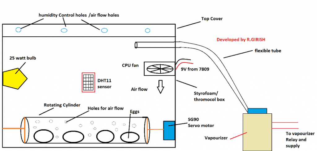
A 25 watt bulb acts as heat source; higher wattage may hurt the eggs in a small container. The humidity is provided by vaporizer, you may use the vaporizer something similar as shown below.
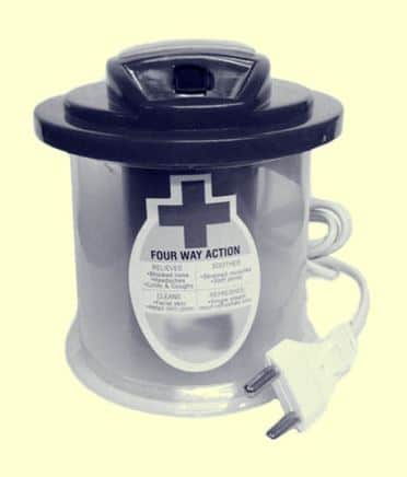
It produces thick stream of steam which will be inlet to incubator. The steam can be carried via any flexible tube.
The flexible tube can be something similar as shown below:

The steam may be inlet from top of the Styrofoam / thermocol box as shown in the apparatus design, so that excess heat will escape though the humidity control holes and less hurting the eggs.
There is a cylinder carrying eggs with several holes around it, connected to a servo motor. The servo motor rotates the cylinder 180 degree every 8 hours thus rotates the eggs.
The rotation of the eggs prevents the embryo sticking to the shell membrane and also provides contact with the food material in the egg, especially at early stage of incubation.
The rotating cylinder must have several numbers of holes so that proper air circulation will be present and also the cylinder must be hollow on both sides.
The rotating cylinder can be PVC tube or cardboard cylinder.
Paste an ice cream stick on both end of the hollow cylinder such that the ice cream stick makes two equal semi circles. Paste the arm of the servo motor at middle of the ice cream stick. On the other side poke a hole and paste a tooth pick firmly.
Insert the tooth pick inside box and paste the servo on opposite wall inside the box. The cylinder must stay horizontal as possible, now the cylinder can rotate as the servo motor rotates.
And yes, use your creativity to make the things better.
If you want to accommodate more eggs make more such cylinders and multiple servo motor can be connected on same control line pin.
The humidity control holes can be made by poking a pencil through the Styrofoam / thermocol box at the top. If you made lot of unnecessary holes or if humidity or temperature is escaping too fast you may cover some of the holes using electrical or duct tape.
The DHT11 sensor is heart of the project which may be placed at the middle of any four sides of incubator (inside) but away from the bulb or humidity inlet tube.
CPU fans can be placed as shown in the apparatus design for air circulation. For proper air circulation use at-least two fans pushing the air in opposite direction, for example: one of the CPU fan pushing downwards and another CPU fan pushing upwards.
Most CPU fan works on 12V but at 9V works just fine.
That’s all about the apparatus. Now let’s discuss on the circuit.
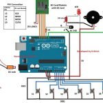
Schematic Diagarm:
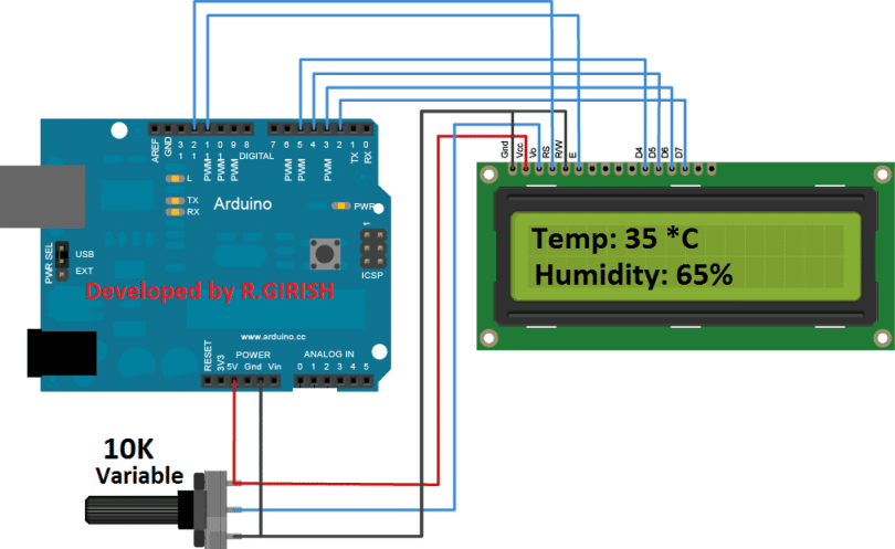
The above circuit is for Arduino to LCD connection. Adjust 10K potentiometer for adjusting LCD contrast.
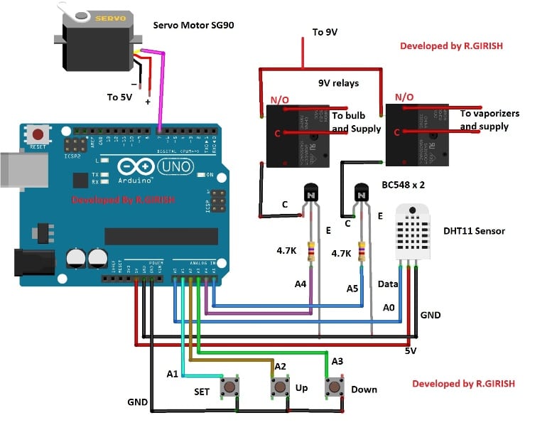
The Arduino is the brain of the project. There are 3 push buttons for setting temperature and humidity. The pin A5 controls the relay for vaporizer and A4 for the bulb. The DHT11 sensor is connected to pin A0. The pins A1, A2 and A3 used for push buttons.
The pin #7 (non-PWM pin) is connected to servo motor’s control wire; multiple servo motors can be connected to pin #7. There is misconception that servo motors works only with PWM pins of Arduino, which is not true. It works happily on non PWM pins too.
Connect a diode 1N4007 across the relay coil in reverse bias to eliminate high voltage spikes while switching on and off.
Power Supply:
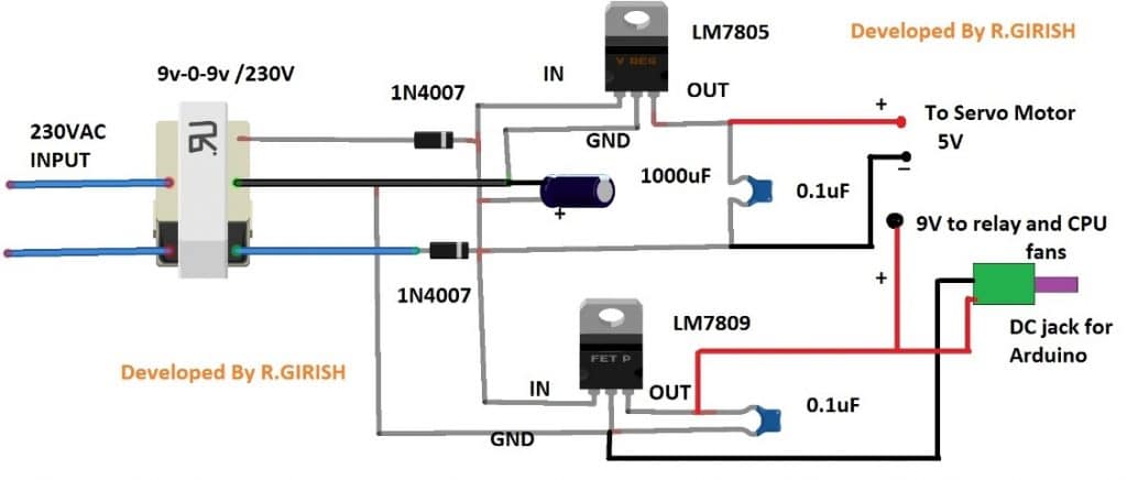
The above power supply can provide 9 V and 5 V supply for relay, Arduino, Servo motor (SG90) and CPU fans. The DC jack is provided for powering the Arduino.
Use heat sinks for the voltage regulators.
That concludes the power supply.
Download the library DHT sensor:
https://arduino-info.wikispaces.com/file/detail/DHT-lib.zip
Program Code:
//------------------Program Developed by R.GIRISH (Improved Version)-------------------//

#include <LiquidCrystal.h>
#include <Servo.h>
#include <dht.h>

// ---------------- PIN DEFINITIONS ----------------
#define DHT11 A0
const int ok     = A1;
const int UP     = A2;
const int DOWN   = A3;
const int bulb   = A4;
const int vap    = A5;

const int rs = 12;
const int en = 11;
const int d4 = 5;
const int d5 = 4;
const int d6 = 3;
const int d7 = 2;

// ---------------- VARIABLES ----------------
int T_threshold = 25;
int H_threshold = 35;

bool T_condition = true;
bool H_condition = true;

unsigned long lastTurnTime = 0;       // for egg turning
unsigned long turnInterval1 = 8UL * 3600UL * 1000UL;   // 8 hours
unsigned long turnInterval2 = 16UL * 3600UL * 1000UL;  // 16 hours

int pos = 0;

LiquidCrystal lcd(rs, en, d4, d5, d6, d7);
Servo motor;
dht DHT;

// ---------------------------------------------------

void setup() {

  pinMode(ok, INPUT_PULLUP);
  pinMode(UP, INPUT_PULLUP);
  pinMode(DOWN, INPUT_PULLUP);

  pinMode(bulb, OUTPUT);
  pinMode(vap, OUTPUT);

  digitalWrite(bulb, LOW);
  digitalWrite(vap, LOW);

  motor.attach(7);
  motor.write(0);

  lcd.begin(16, 2);
  Serial.begin(9600);

  lcd.setCursor(4, 0);
  lcd.print("Digital");
  lcd.setCursor(3, 1);
  lcd.print("Incubator");
  delay(1500);

  lastTurnTime = millis();
}

// ---------------------------------------------------

void loop() {

  // ---------------- SET TEMPERATURE ----------------
  if (T_condition) {
    lcd.clear();
    lcd.setCursor(0, 0);
    lcd.print("Set Temp:");
    lcd.setCursor(0, 1);
    lcd.print(T_threshold);
    lcd.print(" C");

    while (T_condition) {

      if (digitalRead(UP) == LOW) {
        T_threshold++;
        lcd.setCursor(0, 1);
        lcd.print(T_threshold);
        lcd.print(" C ");
        delay(200);
      }

      if (digitalRead(DOWN) == LOW) {
        T_threshold--;
        lcd.setCursor(0, 1);
        lcd.print(T_threshold);
        lcd.print(" C ");
        delay(200);
      }

      if (digitalRead(ok) == LOW) {
        delay(200);
        T_condition = false;
      }
    }
  }

  // ---------------- SET HUMIDITY ----------------
  if (H_condition) {
    lcd.clear();
    lcd.setCursor(0, 0);
    lcd.print("Set Humidity:");
    lcd.setCursor(0, 1);
    lcd.print(H_threshold);
    lcd.print("%");

    while (H_condition) {

      if (digitalRead(UP) == LOW) {
        H_threshold++;
        lcd.setCursor(0, 1);
        lcd.print(H_threshold);
        lcd.print("% ");
        delay(200);
      }

      if (digitalRead(DOWN) == LOW) {
        H_threshold--;
        lcd.setCursor(0, 1);
        lcd.print(H_threshold);
        lcd.print("% ");
        delay(200);
      }

      if (digitalRead(ok) == LOW) {
        delay(200);
        H_condition = false;
      }
    }
  }

  // ---------------- READ SENSOR ----------------
  int chk = DHT.read11(DHT11);

  if (chk != DHTLIB_OK) {
    lcd.clear();
    lcd.setCursor(0, 0);
    lcd.print("Sensor Error");
    lcd.setCursor(0, 1);
    lcd.print("Retrying...");
    digitalWrite(bulb, LOW);
    digitalWrite(vap, LOW);
    delay(1000);
    return;
  }

  float T = DHT.temperature;
  float H = DHT.humidity;

  // ---------------- DISPLAY ----------------
  lcd.clear();
  lcd.setCursor(0, 0);
  lcd.print("Temp:");
  lcd.print(T);

  lcd.setCursor(0, 1);
  lcd.print("Humidity:");
  lcd.print(H);

  // ---------------- TEMPERATURE CONTROL ----------------
  if (T >= T_threshold) {
    digitalWrite(bulb, LOW);
  }
  else {
    digitalWrite(bulb, HIGH);
  }

  // ---------------- HUMIDITY CONTROL ----------------
  if (H >= H_threshold) {
    digitalWrite(vap, LOW);
  }
  else {
    digitalWrite(vap, HIGH);
  }

  // ---------------- EGG TURNING ----------------
  unsigned long now = millis();

  // Turn at 8 hrs
  if (now - lastTurnTime >= turnInterval1 && now - lastTurnTime < turnInterval2) {
    for (pos = 0; pos <= 180; pos++) {
      motor.write(pos);
      delay(25);
    }
  }

  // Turn back at 16 hrs
  if (now - lastTurnTime >= turnInterval2) {
    for (pos = 180; pos >= 0; pos--) {
      motor.write(pos);
      delay(25);
    }
    lastTurnTime = millis();   // Reset cycle
  }

  delay(1000);
}

//-------------- END OF IMPROVED PROGRAM ----------------//
How to operate the Circuit:
· With completed hardware and apparatus setup, power the circuit ON.
· The display shows “set temperature” press up or down button to get the desire temperature and press “set button”.
· Now the display shows “set Humidity” press up or down buttons to get desire humidity and press “set button”.
· It begins the functioning of the incubator.
Please refer internet or get advice from a professional for temperature and humidity level for the eggs.
If you have any specific question regarding this Arduino automatic incubator temperature and humidity control circuit, feel free to express in the comment section. You may receive a quick reply.
How to Setup (Detailed Instructions)
So in the setup function, we initialize the LCD, we attach the Servo to pin 7, we put the bulb and vap pins as OUTPUT, and we make sure they start LOW. Now we show “Digital Incubator” on LCD for some time. So we do this slowly so that user knows the machine is working.
We also store the starting time using millis so that we can later check when we need to rotate the eggs. This is better because we do not manually count seconds inside the loop. That becomes wrong over time.
Setting Temperature
Now we come to the T_condition section. So here we show “Set Temp” on the LCD. Now we want you to press UP or DOWN to increase or decrease the Temperature setpoint.
So we say like this:
- When we press UP then we increase T_threshold by 1.
- When we press DOWN then we decrease T_threshold by 1.
- When we press OK then we stop modifying Temperature and we exit T_condition loop.
We always put delay(200) so that button does not bounce crudely.
So we let user finalize the Temperature first, then after that we go to Humidity.
Setting Humidity
Now we come to H_condition section. So here we show “Set Humidity” on the LCD. We again use UP, DOWN, OK to set H_threshold.
When user presses UP then humidity increases.
When user presses DOWN then humidity decreases.
When user presses OK then humidity setting finishes.
So now we have both Temperature and Humidity thresholds stored inside the program.
Reading Sensor
So after setting, now we start the main loop part where we read DHT11 sensor continuously.
Since DHT11 is slow and sometimes gives errors, so when we read the sensor and then the DHT returns DHTLIB_OK, then we continue normally.
But since there is chance of error, then when DHTLIB_ERROR occurs then system prints “Sensor Error” and stops the outputs temporarily, so bulb and vap remain LOW to avoid overheating.
So we retry again after one second.
Displaying Temperature and Humidity
Now we show the Temperature value on first line and Humidity value on second line. So we do this in every loop so user can see real time values.
Temperature Control Logic
Now we apply our improved temperature control logic:
When DHT.temperature >= T_threshold then bulb is OFF.
When DHT.temperature < T_threshold then bulb is ON.
We do not use big delays like before because those delays used to freeze the system. Now we use simple non-blocking logic, so system responds immediately.
This makes the incubator more reliable and stable.
Humidity Control Logic
Now we apply same style:
When DHT.humidity >= H_threshold then vap is OFF.
When DHT.humidity < H_threshold then vap is ON.
So we keep humidity in the correct range.
Egg Turning System
Now we come to the Servo rotation part. This is the egg turning system.
In the previous old code we manually counted hrs, Min, sec. But now we use millis which is more stable and more correct.
So we do like this:
We store lastTurnTime when setup starts.
We check two intervals: 8 hours and 16 hours.
When now - lastTurnTime >= 8 hours then servo rotates from 0 to 180 slowly.
When now - lastTurnTime >= 16 hours then servo rotates back from 180 to 0.
After rotating back, we reset lastTurnTime so the cycle repeats forever.
So eggs rotate two times every 16 hours cycle.
This is more correct, since using millis gives smooth and stable timing.
Final Loop
Now after all this is finished, we give delay(1000) so loop repeats once per second. This keeps overall system responsive but not too fast.
So entire program works continuously.


Questions & Answers
yes I configured it. as i think I have no the library of DHT11 sensor in my arduino libraries.
OK, then please upload the library.
hello sir! firstly I would like to thank u for such a good work! i really appreciate u. am a beginner to arduino project and when I run the code u wrote above it says “error compiling for board arduino/genuino uno”. what shuold I do please help me!!!
Thank you Samuel, did you configure the “Board Manager” under tools in your Arduino IDE??
Please see the first video in this article for detailed info:
https://www.homemade-circuits.com/2018/10/learning-basic-arduino-programming-tutorial-for-the-newcomers.html
hello sir firstly thank you for sharing very nice skech,i like this project. now i faced one problem is how to replaced turning servo motor and conect a reley for egg turning
Thank you Sajoo, relay is actually not needed. You can use the servo motor itself to turn the eggs. You can configure a mechanism with the motor spindle which will slowly move the eggs positions.
Hi sir,
please can give brief explain action about servo motor timer inside the code ,and how to calculate Sec,Min and Hrs using (If condition).
I am sorry Taraka, I won’t be able to provide help regarding Arduino related circuits since these are written and compiled by another author.
I don’t understand how to give a connection to relay. There are 5 pins and which pins are used for power supply, which is for bulb, which pin ia used by collector of transiator, and two pins left. Where all that pins are used?
Can u explain. So, that I can understand easily
Please check the following article, it will surely help you to understand the details:
https://www.homemade-circuits.com/community/electronic-circuit-forum/how-a-relay-works-in-circuits-how-to-connect-it/
I read this but still don’t find the right solution. Can you please explain the connections of all wire with relay….
Pleaseeeeeeee
I have updated the linked article with the wiring diagram, please check the bottom section of the same article.
There are two terminals of load of and here you show only one.
The other one should be ground??
And relay get direct voltage supply of both positive and negetive terminal??
Is that correct.
Please tell me….
I am very confuse
I see it but I ask there are two terminals of load one is connected and other one will be???
And two terminals of battery are connected with relay….
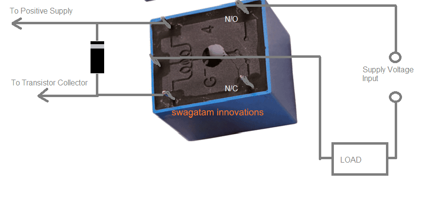
In the diagram you can a box marked as :”load”…it has two terminals, one is connecting to the supply source while the other is connecting with the pole of the relay. The supply source could be a 12V DC or a 220C AC depending on the load’s specifications,
The coil terminals of the relay can be seen connected with the collector of the transistor and the supply positive….make sure to connect a diode across the relay coil
Did you check the diagram that I referred you?
Here it is:
just replace the “Load” with load terminals, and the “supply input” with the supply source which your load requires.
Hello,
good project. thanks.
could you help on the code to have the temperature and humidity sets into MINI and MAXI values.
then is it possible to have number of turning shown on the LCD until the end of the hatching period?
thank you again for you help.
regards
Thank you jxrtv, we are sorry, customized Arduino code is something we are unable to provide at the moment, if possible we may try to update it in near future.
Hi GR,
any chance you could design a custom schematic for a certain price?
Hi Arturs,
Yes we can provide solutions to your customized (schematic and code) for Arduino at 10 rupee per line of code.
Regards
and another question
how i add eeprom in your project?
Hi Martin,
You can learn about EEPROM here :https://www.homemade-circuits.com/introduction-eeprom-arduino/
Regards
how can i do this?
OK I want to try thank you
Hi rahokos,
Everything illustrated here works fine, please check your connections and adjust display contrast.
Regards
Hello again a question lcd does not work with arduino uno thank you
Hello what type relay use you thank you?
ordinary 400 ohm type of relay as shown at the end of this article
https://www.homemade-circuits.com/how-a-relay-works-in-circuits-how-to-connect-it/
At first
I would like to extend my thanks and appreciation to you
Second, let me say that I have dht11 and do everything but give me no sensor data.
What is the problem, although the sensitive works in other programs
A noticeable four-limb was recommended for the ground and hot and No. 2 for the data
Hi khaled
Please check the pin diagram for your DHT11 sensor, there are DHT11 with different pin-outs, connect pull down resistors if necessary.
Regards
Thank you very much, we are glad to assist you. Mr. GR will reply you soon
SIR WHEN IAM UPLOADING THE PROGRAM
IAM FACING SOME PROBLEM
sketch_mar25c:30: error: ‘dht’ does not name a type
PLS HELP RESOLVE THE PROBLEM, THANKS IN ADVANCE
Hi RIYAS,
You have to download the library file and add to your compiler.
Link: https://drive.google.com/open?id=1aWuF115pMaZbySQS2CIHBxJiPSM1ezhE
Regards
Mr. GR will reply you soon….
the link of dht library is broken
told me this
Arduino: 1.8.5 (Windows 8.1), Board: “Arduino/Genuino Uno”
C:\Users\ghost\Desktop\sketch_mar26a\sketch_mar26a.ino:3:17: fatal error: dht.h: No such file or directory
#include
^
compilation terminated.
exit status 1
Error compiling for board Arduino/Genuino Uno.
This report would have more information with
“Show verbose output during compilation”
option enabled in File -> Preferences.
Hi martin,
Try this link: https://drive.google.com/open?id=1aWuF115pMaZbySQS2CIHBxJiPSM1ezhE
Regards
thank you very much
god bless you
hi budy
I am requesting you to use the Arduino project file in the original format of the program
Because I do not know the distance} {}
Hi matin,
I didn’t understood “I do not know the distance} {}”.
Copy the code and past to the IDE and save it on your desktop, you will get the .ino file.
Regards
Hi Matin, I’ll forward this question to Mr. GR, he will reply you soon.
sir i am facing the problem with this code
This report would have more information with
“Show verbose output during compilation”
enabled in File > Preferences.
Arduino: 1.0.6 (Windows NT (unknown)), Board: “Arduino Uno”
sketch_mar26b:30: error: ‘dht’ does not name a type
sketch_mar26b.ino: In function ‘void loop()’:
sketch_mar26b:121: error: expected primary-expression before ‘.’ token
sketch_mar26b:124: error: ‘DHTLIB_ERROR_CONNECT’ was not declared in this scope
sketch_mar26b:133: error: expected primary-expression before ‘.’ token
sketch_mar26b:136: error: expected primary-expression before ‘.’ token
sketch_mar26b:137: error: expected primary-expression before ‘.’ token
sketch_mar26b:140: error: expected primary-expression before ‘.’ token
sketch_mar26b:145: error: expected primary-expression before ‘.’ token
sketch_mar26b:148: error: expected primary-expression before ‘.’ token
sketch_mar26b:153: error: expected primary-expression before ‘.’ token
sketch_mar26b:156: error: expected primary-expression before ‘.’ token
sketch_mar26b:161: error: expected primary-expression before ‘.’ token
sketch_mar26b:164: error: expected primary-expression before ‘.’ token
I’ll forward this question to Mr. GR for a reply.
please send me any data regarding this matter thank you for your helping
This is very nice code, but one thing that i notice in this code, every time when I power on I need to set the value of temperature and humidity.
I want to ask you sum thing , after power on if I am not setting the value of Temperature and humidity within a 5 minute It will take the default value. Can you do this.
Good work Keep it up……
thank you,
Hi nitin,
You should not turn OFF the circuit during the incubation period, You can use a cheap computer UPS if there is frequent power cuts.
Regards
but sometime it happens that, there is a power cut for fraction of second and at that time if no one is available to set the temperature and humidity, at that time it is going to be useful. I think so,
Thanks nitin, I am glad you liked it…I’ll forward this question to Mr.GR, and he will try to reply you soon…thanks for posting
1,how can i connect the lcd to arduino uno
2,which tpe of arduino uno you are used
thank you for your support