• Skip to main content
  • Skip to primary sidebar

Homemade Circuit Projects

Need circuit help? Post them in the comments! I've answered over 50,000!

Blog | Categories | About | Contact | Calculators-online
You are here: Home / Voltage Control and Protection / Simple Refrigerator Protector Circuit

Simple Refrigerator Protector Circuit

Last Updated on January 2, 2024 by Swagatam 104 Comments

This simple refrigerator protector circuit is actually a delay ON timer circuit which makes sure that whenever a power failure occurs or in case abrupt power fluctuations take place, the refrigerator is never allowed to switch ON instantly, rather after a delay of a few moments.

Table of Contents
  • Conventional Protection Features
  • Circuit Operation
  • PCB Design (Triac)

Conventional Protection Features

Today most modern refrigerators are equipped with a protection feature which prevents the fridge from suddenly switching ON or OFF due to sudden power fluctuations or a sudden power restoration.

However, for those fridges which are not equipped with this feature, the following simple delay ON timer circuit can be applied to enable the refrigerator to switch ON after a certain delay, and only when the mains power has become stable.

Until this happens the circuit keeps the fridge switched OFF and monitors until the power has returned to a perfectly normal status.

NOTE: Please use a 50 ohm 1 watt resistor in series with mains input line, otherwise the zener diode may burn during power switch ON.

refrigerator protector circuit with triac timer

Circuit Operation

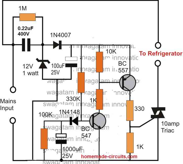
Referring to the above shown refrigerator protection circuit, we are able to witness a two transistor circuit which forms a very basic yet effective delay ON timer circuit, meaning this circuit switches ON its output after some delay, after power is applied to it.

The power supply to the circuit is derived from the mains via a transformerless power supply circuit
which is appropriately stabilized at 12V and fed to the delay circuit.

Whenever power is switched ON, may it be during the first initialization, or during a power failure situation, the associated 1000uF capacitor prevents the BC547 from switching ON at the onset, which in turn keeps the BC557 and the triac switched OFF. The load is therefore unable to receive power and stays switched OFF too.

However, the 1000uF now gradually begins charging via the 330K resistor and when the potential difference across it reaches the approximate total of transistor's biasing limit plus the emitter zener value (0.6 + 3 = 3.6V), the transistor begins switching ON which prompts the BC557 also to switch ON.

The triac now begins acquiring the required gate voltage and within moments switches ON the fridge.

The 1000uF capacitor stays charged as long as power is available to the circuit, and during power failures the capacitor discharges through the parallel 100k resistor so that it can get into the standby mode for the next delay ON cycle operation.

The time delay period can be accomplished by appropriately selecting the values of the 330K resistor, the 1000uF capacitor and the 3V zener diode, as per the user's preference.

This concludes the explanation for the proposed simple refrigerator protection circuit, for any related query please feel free to use the comment box.
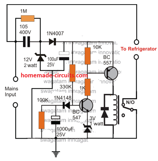
Using Relay

The above design can be used with a relay also as demonstrated below:

fridge protect

PCB Design (Triac)

refrigerator protector PCB design

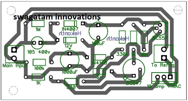
WARNING: CIRCUIT IS NOT ISOLATED FROM MAINS... STRICT PRECAUTIONS MUST BE OBSERVED WHILE HANDLING THE DEVICE, WHILE IT'S IN AN UNENCLOSED CONDITION.

You'll also like:

  • 1.  Mains AC Overload protection Circuit for Voltage Stabilizers
  • 2.  USB 5V To 24V DC to DC Boost Power Regulator Module
  • 3.  Power Factor Correction (PFC) Circuit – Tutorial
  • 4.  How RCCB Works [with Circuit Diagram]
  • 5.  Automatic Voltage Regulator (AVR) Analyzer
  • 6.  How to Make a 220V to 110V Converter Circuit

About Swagatam

I am an electronics engineer with over 15 years of hands-on experience. I am passionate about inventing, designing electronic circuits and PCBs, and helping hobbyists bring their projects to life. That is why I founded homemade-circuits.com, a website where I share innovative circuit ideas and tutorials. Have a circuit related question? Leave a comment.... I guarantee a reply!

Previous Post: « How Electret Microphones Work – Full Tutorial and Diagram
Next Post: Temperature Controlled DC Fan Circuits »

Reader Interactions

Comments

  1. ahmed hasan says

    September 26, 2024 at 6:42 pm

    Hi sir
    For second circuit, if we need to use relay 24V, what will be changed in the circuit for Zener 12V, Zener 3V and the resistors 10K and 1K.
    What is the resistor for the 24V coil that will be used with her?
    Thank you

    Reply
    • Swagatam says

      September 26, 2024 at 7:01 pm

      Hi Ahmad,
      If you want to use a 24V relay, then you just need to change the 12V zener with a 24V zener diode, that’s all, nothing else needs to be changed. Also, you can can connect a 5 ohm 1 watt resistor in series with one of the input AC terminals, just for limiting the initial inrush current.

      Reply
      • ahmed hasan says

        September 26, 2024 at 7:18 pm

        Thank you very much, sir What about 24V coil resistor? how much value must be used

        Reply
        • Swagatam says

          September 27, 2024 at 7:30 am

          Ahmad, no coil resistor is used for the relay, only a 1N4007 diode is used parallel to the coil…

          Reply
          • ahmed hasan says

            September 28, 2024 at 6:41 pm

            sorry sir, I mean the XL of coil how much to be used

            Reply
            • Swagatam says

              September 28, 2024 at 6:57 pm

              Do you mean the coil resistance? Select a relay which has a coil resistance as high as possible, with a contact current rating that can handle the fridge load comfortably.

              Reply
              • ahmed hasan says

                September 28, 2024 at 9:39 pm

                yes I mean that
                thank you

                Reply
                • Swagatam says

                  September 29, 2024 at 7:38 am

                  Ok, so you can check the datasheets of the various 24V relays and select the one whose contact rating is sufficient to handle your fridge load, and also the coil has maximum resistance. You have to compare the relays from different companies to find the one which offers higher coil resistance and yet a reasonable contact current rating.

                  Reply
  2. Ali says

    February 10, 2024 at 10:50 pm

    Dear Sir Swagatam
    I hope you are doing well
    I would like to request your instruction in this regard: upon removing the following components (R: 1 MR, C: 105/400V, D: 1N4007, Z: 12Volt 2W, C: 100uf/25V) from your relay-based circuit and applying a 220/12V adapter to the circuit, would the circuit effectively disconnect the output of 220V if the mains supply drops to low voltages, such as 180V? Additionally, I am interested in knowing whether the circuit would remain operational in the event of a surge in voltage, such as 250V or higher. I would greatly appreciate your response.
    Truly yours
    Ali

    Reply
    • Swagatam says

      February 11, 2024 at 9:50 am

      Dear Ali,
      No, the above circuit will not cut off at high or low voltage situations. It is just a delay on timer circuit which will delay the switch ON of the load whenever AC power fails and restores back.
      You can refer to the following article instead, for the high and low voltage cut off with delay ON feature
      https://www.homemade-circuits.com/mains-ac-home-protector-circuit/

      Reply
  3. Muema says

    February 10, 2024 at 10:00 pm

    Would you kindly recommend the SMD components for this PCB?

    Reply
    • Swagatam says

      February 11, 2024 at 9:37 am

      You can ask the spare part retailer to provide you the SMD versions of the components indicated in the diagram.

      Reply
      • Muema says

        February 16, 2024 at 2:46 pm

        Noted. Thank you

        Reply
  4. Don says

    October 10, 2023 at 4:38 pm

    Would this work as a delay on for a refrigerator compressor? Connected before the compressor relay? What combination of parts would equal a 1 to 3 minute delay for a 120 v, 15 LRA compressor?

    Reply
    • Swagatam says

      October 10, 2023 at 5:27 pm

      Yes, it will work, if the wiring is done correctly. The delay time may need to be adjusted with some practical experimentation. Either the 330K resistor or the 1000uF capacitor can be tweaked individually, or together to get the desired delay ON timing.

      Reply
  5. reagan says

    January 13, 2023 at 12:35 am

    sir i have been given a task to design and manufacture a low cost simple fridge surge device . would you please help me on few steps i need to take to design this..?..thanks in advance sir

    Reply
    • Swagatam says

      January 13, 2023 at 9:00 am

      Hi Reagan, You can try one of the circuits explained above, they are one of the best forms of fridge surge suppressor with timer.

      Reply
      • Reagan says

        January 15, 2023 at 7:27 pm

        Thanks sir… I will be here for more queries sir ????

        Reply
  6. Vladimir says

    November 1, 2022 at 11:41 am

    hello Swagg, my name is Vladimir. Can you help me to make a circuit that will use (50amps) ssd relay to connect battery to sine way inverter with delay while capacitors inside inverter being charged by resistor to avoid big spark on input terminals and damage inverter if connect it straight to battery. Thanks.

    Reply
    • Swagatam says

      November 1, 2022 at 1:00 pm

      Hello Vladimir,
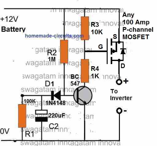
      You can try implementing the following diagram:
      " rel="ugc">comment image

      Reply
  7. Redge says

    September 12, 2022 at 2:43 pm

    Hi Swagatam

    What should the voltage of the relay coil be?

    Thank you

    Redge

    Reply
    • Swagatam says

      September 12, 2022 at 5:07 pm

      Hi Redge,
      Since a 12V zener diode is used in the power supply, so the relay coil will be also 12V rated.

      Reply
  8. Redge says

    September 12, 2022 at 12:01 pm

    Hi
    I am an electronics dummy, but I like playing around with it. Could you please tell me the exact specs of the 50 ohm 1watt resistor in series with mains and also the relay – I will use it for a 240V fridge that draws about 140watt running and 900watt starting.
    How long will this capacitor take to discharge?
    Thank you for your website and for this circuit!
    Regards
    Redge

    Reply
    • Swagatam says

      September 12, 2022 at 12:42 pm

      Hi,
      The 50 ohm resistor should be a wire-wound type resistor. It could rated at 1 watt or 2 watts. I would prefer using 2 watts. For more safety for the zener diode, you can use a 2 watt zener diode so that it remains unaffected by the initial input current surge through the 105/400V capacitor.
      Remember this circuit is not isolated from mains AC and is therefore very dangerous to touch in an open and powered condition.

      Reply
  9. George foster says

    June 6, 2022 at 1:48 pm

    Hi i am looking at the Refrigerator protector circuit .
    Do you have the circuit board for this pls advise.

    Regards
    George Foster.

    Reply
    • Swagatam says

      June 6, 2022 at 1:56 pm

      Sorry, No, I do not have a ready PCB for this project.

      Reply
      • Reagan says

        January 15, 2023 at 7:35 pm

        Hi, would you design me one circuit (with a Triac or relay) ? I want to purchase it from you sir.

        Reply
        • Swagatam says

          January 15, 2023 at 7:39 pm

          Hi Reagan, sorry making it practically may not be possible for me. I can guide you with the construction and testing of the unit if you want to build it.

          Reply
    • George foster says

      June 6, 2022 at 2:02 pm

      Hi no problem thank you.

      Reply
  10. A Jegannathan says

    April 8, 2022 at 11:02 pm

    May I use triac 400 V 12 A instead 10 A? Please clarify my doubt sir.

    Reply
    • Swagatam says

      April 9, 2022 at 9:56 am

      You can use it!

      Reply
      • A Jegannathan says

        April 9, 2022 at 5:39 pm

        Thank you very much sir.

        Reply
        • Swagatam says

          April 9, 2022 at 5:55 pm

          You are welcome A Jegannathan!

          Reply
  11. saleem faeq says

    February 22, 2021 at 2:57 am

    Hi I SALEEM FAEQ from Iraq-Baghdad I like this field thanks for all at this website>

    Reply
    • Swagatam says

      February 22, 2021 at 10:52 am

      You are welcome!

      Reply
      • Sajida Mahmood says

        October 19, 2021 at 2:30 pm

        I have tried you “Simple fridge on delay circuit”, it is working fine but one big drawback is there, when circuit is on and fridge working, suddenly power goes off and within second restored, that time this circuit cut off the power but switching on the fridge without any delay (as capacitor hasn’t discharged yet). How to overcome this issue as this is very dangerous for fridge?

        Reply
        • Swagatam says

          October 19, 2021 at 5:05 pm

          You can try adding a PNP transistor across the 1000uF capacitor as shown in the following diagram. I have also added a 4k7 bleeder resistor across the supply terminals so that 100uF filter capacitor can discharge quickly and switch ON the PNP transistor whenever mains AC fails. I have also reduced the input 0.22uf/400V to protect the zener diode from surge currents.

          comment image" alt="improved fridge protector for fluctuating mains AC " />

          Reply
  12. Rashid Ansari says

    February 15, 2021 at 10:30 pm

    Hello Sir,
    Hope you r donig fine.
    Sir I want to know about Solar Hydro Panels working. How it generates drinking water frome air and can we construct it with an ordenery solar panel of 12V, 150 W ?

    Please if you can help.
    Thanks in advance

    Reply
    • Swagatam says

      February 16, 2021 at 1:43 pm

      Hello Rashid,
      Solar hydropanel consists of solar cells, along with areas that can absorb water vapor from atmosphere. The solar cell voltage is used for driving many small motors which act like exhaust fans, and help to suck air into the water absorbing surface, which absorb the water content from the atmosphere and channelize them into water storage tanks.

      You can definitely use your 12 V panel to build a solar hydropanel, as described in my above explanation.

      Reply
  13. Haitham hashim says

    January 10, 2021 at 8:32 pm

    Thanks for your answer

    Reply
  14. haitham hashim says

    January 10, 2021 at 4:58 pm

    excellent page contains important things needed by hobbyist and professional in electronics .
    outstanding effort .i like this page and i will visit it several times .thanks

    Reply
    • Swagatam says

      January 10, 2021 at 6:51 pm

      Thank you, and glad you found the page informative…

      Reply
  15. Asim Kumar Ash says

    January 7, 2021 at 12:32 am

    I am an retired electrical diploma eng.(electrical).now I have enough time.i want to get training on different electrical./electronic circuit diagram of domestic equip.how u can help me.If u help me then I will be very grateful to u.After getting knowledge I want to give the services to the people.
    Thank u

    Reply
    • Swagatam says

      January 7, 2021 at 12:59 pm

      No problem, you can ask specific questions, I will try my best to help you with the answers.

      Reply
  16. Nisar Gul says

    August 28, 2020 at 12:07 am

    Dear Swagatam,
    I have build this circuit on veroboard but there is problem with this circuit. Output of the power supply portion is about 11.5v while output at relay terminals remain clamped at 6.2v no matter what resister and capacitor I use for delays. I have wait for 10 to 12 minutes with 150k & 1000uF capacitor but the voltage remains at 6v and 12v relay is not operating.

    Reply
    • Swagatam says

      August 28, 2020 at 10:17 am

      Dear Nisar, the problem is not in the circuit, it may be in your relay coil. Make sure it is not less than 400 ohm. You must always begin by checking the basic design, and then proceed with the final design. Please remove the relay and connect a LED with 1k series resistor across the collector/ground of the PNP. The LED should light up after the set delay, which will prove the correct working of your circuit….if it doesn’t your circuit may be having problems, which you will have to troubleshoot yourself….the circuit is thoroughly tested OK.

      Reply
      • Swagatam says

        August 28, 2020 at 10:20 am

        but yes there’s one thing missing in the circuit….the C1 must have a 50 ohm 2 watt resistor in series otherwise the zener may burn, alternatively you may have to increase the zener wattage to 2 watt or 5 watt.

        Reply
    • Nisar Gul says

      August 29, 2020 at 10:56 pm

      Dear Swagatam,
      I have checked first basic design with LED as you told and the LED light up. When I checked the voltage, found it is around 6v. I need minimum 9v to operate 12v relay. Anyway I am going to check my circuit again thoroughly. Thanks for your help.
      Regards
      Nisar

      Reply
      • Swagatam says

        August 30, 2020 at 9:28 am

        Hi Nisar, I hope you have connected a 1k series with the LED. Please try a bridge rectifier instead of a single diode rectifier at the input side of the power supply, and the check the voltage again…The voltage may be dropping due to lack of current.

        The best alternative way is to use a 12V AC to DC adapter for supplying the DC input to the circuit, which will work without any hassles.

        Reply
  17. Nisar Gul says

    August 24, 2020 at 10:53 pm

    Dear Swagatam,
    How much time delay will achieved with this circuit?
    Suppose if mains 220v drops (let say 130v), then what happened?
    I want a 3 minutes delay, what should I replaced?
    Regards
    Nisar

    Reply
    • Swagatam says

      August 25, 2020 at 10:26 am

      Hello Nisar, the delay will depend on the 1000uF and 330 k resistor values, you can change them accordingly to get the desired delay time. The circuit will switch ON the fridge after the set delay, each time the fridge is switched OFF due to voltage failures.

      Reply
  18. Teb's says

    July 14, 2020 at 2:38 am

    Plz sir the relay to be used in the refrigerator protection is it ac or dc and plz what is the suitable amps to use

    Reply
    • Swagatam says

      July 14, 2020 at 6:40 pm

      It is a DC relay.

      Reply
  19. ajay says

    May 17, 2020 at 10:30 pm

    ” Please use a 50 ohm 1 watt resistor in series with mains input line, otherwise the zener diode may burn during power switch ON ”

    Hi swagatham thanks for works – 50 ohm 1 watt resistor – where it exactly to be connected

    Reply
    • Swagatam says

      May 18, 2020 at 9:29 am

      Hi Ajay, you can connect it anywhere in series with the input 220V supply line, it can be in the phase line or the neutral line does not matter. Instead of using a single 50 ohm, use 3nos 15 ohm 1 watt resistor in series

      Reply
  20. M. Iqbal says

    March 9, 2020 at 4:52 pm

    Hi Sawag, can we use VR insted of fixed resistor for adjusting delay time.

    Reply
    • Swagatam says

      March 9, 2020 at 6:12 pm

      yes you can, replace the 330k with a 470 k or 1M pot. make sure to add a 10k resistor in series with the pot

      Reply
  21. Alireza says

    December 15, 2019 at 7:05 pm

    Hi. I do have a question.
    if by any reason, the circuit fail, does it inject 220 volt into output? or it will be higher than 220 volts?

    Reply
    • Swagatam says

      December 15, 2019 at 8:10 pm

      Hi, if it fails, the refrigerator will either get a constant 220V supply or will be completely shut off, it cannot produce more than 220V because there’s no voltage boosting facility in the design.

      Reply
      • Alireza says

        December 16, 2019 at 10:43 am

        so in worst case it causes no harm. it may only stop functioning. Am I right?

        Reply
        • Swagatam says

          December 16, 2019 at 1:33 pm

          Yes that’s correct!

          Reply
  22. Carlos says

    December 6, 2019 at 12:22 am

    Hi, thanks for the quick response. You could modify the circuit with a relay … Thank you very much

    Reply
    • Swagatam says

      December 6, 2019 at 11:19 am

      I have updated it in the article…

      Reply
      • Alex says

        December 6, 2019 at 10:30 pm

        Thanks Swag. I find your articles and circuits very detailed and informative. Especially to an electronics enthusiast such as myself.
        Question: What should i change in the in the above refrigerator protector circuit when the input voltage is 110V.
        Thanks in advance

        Reply
        • Swagatam says

          December 7, 2019 at 10:12 am

          Thanks Alex, for that you may have to employ 12V transformer based power supply, and modify the transistor stage so that the when the 12V drops to an equivalent 10V the relay trips OFF

          Reply
  23. Carlos says

    December 5, 2019 at 2:23 am

    Hello good afternoon. I like the circuit, but in my case it would be better with a relay … Because I never had much confidence in a triac .. Thank you in advance.

    Reply
    • Swagatam says

      December 5, 2019 at 11:44 am

      Thank you, for relay operation you can simply replace the 330/1K resistor at the collector of BC557 with a relay coil and with freewheeling diode

      Reply
  24. Cecilio Rodriguez says

    March 6, 2019 at 10:38 pm

    sir,
    Can I use this circuit in widow type ac (aircondition)?
    thanks and more power to you.

    Reply
    • Swagatam says

      March 7, 2019 at 6:20 am

      Hi Cecilio, yes you can use it for ACs also, in fact it can be used for any desired load!

      Reply
  25. Noel says

    July 18, 2018 at 2:49 pm

    Hi
    Do you have a circuit for a 100w bass guitar amp.
    Regards

    Reply
    • Swagatam says

      July 18, 2018 at 3:52 pm

      Hi, you can try the following concept

      https://www.homemade-circuits.com/how-to-make-outstanding-home-theater/

      you can replace the shown amplifier design with the following circuit
      https://www.homemade-circuits.com/how-to-make-simplest-100-watt-mosfet/

      Reply
  26. Noel says

    July 13, 2018 at 7:30 pm

    Hi sir,
    Hope you are well.
    Just want to know if you have a circuit to test eeproms.
    Regards

    Reply
    • Swagatam says

      July 13, 2018 at 8:29 pm

      Hi Noel, I have seen a few of them in some old magazines with me, if possible I’ll publish them here, but I am not sure whether the designs are still relevant or not.

      Reply
      • Noel says

        July 13, 2018 at 8:31 pm

        Thanks appreciate it

        Reply
  27. Noel says

    June 29, 2018 at 10:37 am

    Thank you much appreciated

    Reply
    • Swagatam says

      June 29, 2018 at 11:49 am

      You are welcome!

      Reply
  28. Noel says

    June 29, 2018 at 2:23 am

    Hi sir,
    With regards to the high/low mains cut off circuit using two relays can the out put be connected direct to the db thereby protecting all appliances or must it be connected to each individual appliance.
    Regards

    Reply
    • Swagatam says

      June 29, 2018 at 10:34 am

      Hi Noel, the 2 relay circuit is not required, you can use the single relay circuit and configure the relay contact in series with one of your DP lines and then you can apply it for safeguarding all the associated appliances.

      Reply
  29. Noel says

    June 27, 2018 at 6:15 pm

    Hi,
    Can you design a circuit that can be used in a db box so that if there is load shedding or some power surge the entire plug points go off until voltage is stabilized at 240v when power comes back on.
    Regards

    Reply
    • Swagatam says

      June 27, 2018 at 8:48 pm

      Hi, I think you could apply the concept discussed in the following article and see if it suits your requirement.

      https://www.homemade-circuits.com/highly-accurate-mains-high-and-low/

      Reply
      • Noel says

        June 27, 2018 at 11:21 pm

        Hi
        Thanks for the invaluable info really appreciate it.
        Regards

        Reply
        • Swagatam says

          June 28, 2018 at 10:34 am

          It’s my pleasure!

          Reply
  30. Noel says

    June 25, 2018 at 9:13 am

    Hi
    Can the fridge protection circuit also be use for other items like tvs, other electronic equipment.
    Regards

    Reply
    • Swagatam says

      June 25, 2018 at 9:29 am

      yes it can be used for any desired appliance or gadget.

      Reply
  31. Noel says

    June 25, 2018 at 7:20 am

    Sir,
    Regarding the fridge protection circuit what are the wattage of the resistors.
    Thanks

    Reply
    • Swagatam says

      June 25, 2018 at 8:53 am

      Noel, all resistors are 1/4 watt rated

      Reply
  32. KSR Discoveries says

    April 8, 2017 at 2:53 pm

    dear sir i want this circuit for giving input to 12 V relay

    Reply
    • Swagatam says

      April 9, 2017 at 5:37 am

      please modify the above design as per the following design

      https://www.homemade-circuits.com/2013/02/make-this-simple-delay-on-circuit.html

      Reply
  33. Jade Mark Talaboc says

    August 8, 2016 at 10:05 pm

    hello Swagatam,

    Can I use 225 capacitor instead of 105?

    Reply
    • Swagatam says

      August 9, 2016 at 7:58 am

      hello jade, you can try it, if the triac fires correctly with it then it you can continue with it…..

      Reply
  34. Anirudh Kundu says

    August 3, 2016 at 6:07 pm

    Sir i made a refrigerator delay on circuit using a 555 ic. I'm using a transformer based power supply and regulating it via 7812.

    The problem am facing is i'm using a 25volts 1000mf cap with the transformer and the bridge rectifier.

    When there is a change of power from genset to mains power, the circuit doesn't shut off as the change takes place in a second and the capacitor compensates this no power state and doesn't shut the circuit off.
    I just wanted to know what rating of bleed resistor should i use. And should i use it before the ic 7812 or after the ic 7812.

    Thanks.

    Reply
    • Swagatam says

      August 4, 2016 at 10:36 am

      Anirudh, you can try with a 1K 1/4 watt directly in parallel with the 1000uF capacitor and see the response

      Reply
  35. Sherwin Baculi says

    July 20, 2016 at 11:40 am

    Sir. The triac needs a heatsink?

    Reply
    • Swagatam says

      July 20, 2016 at 2:21 pm

      Yes it will need a heatsink

      Reply
    • Jade Mark Talaboc says

      August 3, 2016 at 9:52 pm

      hello swagatam,

      the 3v, 1watt zener is not available here in my place. can i parallel 2x3V,1/2W zener instead?

      Reply
    • Swagatam says

      August 4, 2016 at 10:49 am

      hello jade,

      1 watt is not required….1/2watt will be fine without issues.

      Reply
    • Jade Mark Talaboc says

      August 4, 2016 at 9:35 pm

      Thank you so much sir

      Reply
  36. NvD says

    July 19, 2016 at 11:00 am

    thank you very much sir

    Reply
  37. NvD says

    July 19, 2016 at 6:55 am

    last question sir..i think i m not disturbing you..in below circuit

    https://www.homemade-circuits.com/2016/07/touch-free-faucet-circuit.html

    sirwhat is the value of resister R8 and R9 (not shown in fig)..sir is thereany substitute for 1uF 16v (cant find in store)..p1 and p2 are variable resistance is it right..is all resisters 1/4watt…i am going to make this circuit..hope itworks

    Reply
    • Swagatam says

      July 19, 2016 at 10:25 am

      you can use 10K for both the resistors
      the 1uF is a filter capacitor so it's not critical, you can use any other higher value…
      p1/p2 are presets, or trimpots
      all resistors are 1/4 watt

      Reply
  38. Syed Ameer Hamza Askari says

    July 18, 2016 at 12:14 pm

    Sir mera laptop charge nahi ho raha hay mene dosra adptor lagaya tu thori dair charge howa phir nahi ho raha hay agar ap ko is k baray me maloom hay tu please help kar dain thank u.

    Reply
    • Swagatam says

      July 19, 2016 at 3:55 am

      Syed, the problem could be with the battery or the internal laptop circuit…can't say precisely without checking.

      Reply
  39. NvD says

    July 17, 2016 at 9:37 am

    sir pls help
    In your pir (https://www.homemade-circuits.com/2014/09/automatic-pir-controlled-fan-circuit.html) you mention that there is a delay in switching of fan..i dont want that delay..i need to switch off instantly..pls give me changes in circuit..so that i can use it for automatic faucet to prevent wastage of water

    Reply
    • Swagatam says

      July 17, 2016 at 3:01 pm

      NVD, you can remove the 470uF capacitor for eliminating the delay effect

      Reply

Need Help? Please Leave a Comment! We value your input—Kindly keep it relevant to the above topic! Cancel reply

Your email address will not be published. Required fields are marked *

Primary Sidebar

Subscribe to New Circuit Ideas

Categories

  • Arduino Projects (87)
  • Audio and Amplifier Projects (132)
  • Automation Projects (17)
  • Automobile Electronics (101)
  • Battery Charger Circuits (83)
  • Datasheets and Components (104)
  • Electronics Theory (143)
  • Free Energy (37)
  • Games and Sports Projects (11)
  • Grid and 3-Phase (19)
  • Health related Projects (25)
  • Home Electrical Circuits (12)
  • Indicator Circuits (14)
  • Inverter Circuits (87)
  • Lamps and Lights (142)
  • Meters and Testers (69)
  • Mini Projects (46)
  • Motor Controller (64)
  • Oscillator Circuits (27)
  • Pets and Pests (15)
  • Power Supply Circuits (108)
  • Remote Control Circuits (50)
  • Security and Alarm (64)
  • Sensors and Detectors (101)
  • Solar Controller Circuits (59)
  • Temperature Controllers (42)
  • Timer and Delay Relay (49)
  • Transmitter Circuits (29)
  • Voltage Control and Protection (37)
  • Water Controller (36)

Calculators

  • Battery Back up Time Calculator
  • Capacitance Reactance Calculator
  • IC 555 Astable Calculator
  • IC 555 Monostable Calculator
  • Inductance Calculator
  • LC Resonance Calculator
  • LM317, LM338, LM396 Calculator
  • Ohm’s Law Calculator
  • Phase Angle Phase Shift Calculator
  • Power Factor (PF) Calculator
  • Reactance Calculator
  • Transistor Astable Calculator
  • Transistor base Resistor Calculator
  • Voltage Divider Calculator
  • Wire Current Calculator
  • Zener Diode Calculator
  • Filter Capacitor Calculator
  • Buck Converter Calculator
  • Boost Converter Calculator
  • Solar Panel, Inverter, Battery Calculator
  • Wire Current Calculator
  • SMPS Transformer Calculator
  • IC SG3525, SG3524 Calculator
  • Inverter LC Filter Calculator

People Also Search

555 Circuits | 741 Circuits | LM324 Circuits | LM338 Circuits | 4017 Circuits | Ultrasonic Projects | SMPS Projects | Christmas Projects | MOSFETs | Radio Circuits | Laser Circuits | PIR Projects |

Recent Comments

  • Swagatam on Real MPPT Solar Charger Circuit Using Arduino, LCD, and Manual/Auto Switch
  • Obaidullah Khan on Real MPPT Solar Charger Circuit Using Arduino, LCD, and Manual/Auto Switch
  • Swagatam on 2 Compact 12V 2 Amp SMPS Circuit for LED Driver
  • Alan Bishop on AC Motor Speed Controller Circuits using Back EMF
  • Swagatam on Real MPPT Solar Charger Circuit Using Arduino, LCD, and Manual/Auto Switch

Company

  • Privacy Policy
  • Cookie Policy
  • About Me
  • Contact
  • Disclaimer
  • Copyright
  • Videos
  • Sitemap

Social Profiles

  • Twitter
  • YouTube
  • Instagram
  • Pinterest
  • My Facebook-Page
  • Quora
  • Stack Exchange
  • Linkedin
  • © 2025 · Swagatam Innovations