In this article we study how potentiometers work and try to understand how to connect potentiometers in electronic circuits.
How Potentiometers Work
Potentiometers, or pots as these are called in short form are passive electronic devices which are basically just variable resistors, or resistors whose values can be altered from zero maximum within the given range (potentiometer value) manually.
For example a 10k pot will have a range from 0 to 10000 ohms and its value can be set anywhere within this window, depending upon the selected rotational position of the pt shaft.
The variable function of a pot is implemented by rotating the shaft of the pot either clockwise or anticlockwise causing its relevant terminals to determine an increasing or decreasing resistance values and vice versa.
A potentiometer normally has three terminals or leads across which the variable resistance output can be measured and determined for a given electronic circuit application.
Looking at the given simulation, we find that when the shaft of the pot is rotated, the resistance changes across the either sides of the center lead at an opposite rate.
In other words, for instance a clockwise rotation of the shaft may continuously and proportionately produce an increasing resistance between its center and right side leads, while a proportionately decreasing resistance between its center and the left hand side lead.
The above response is thus differential across the two sides of the center lead of the pot. The resistance may be exactly equal across the left and the right leads with respect to the center lead, if the shaft is positioned approximately at the center of the rotational dial.
How to Connect a Pot Using three Leads
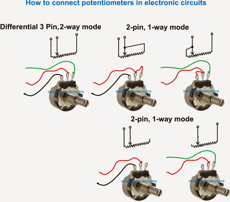
Since a Potentiometer normally has three leads, it can be used either in a 2-way deferentially varying resistance mode or in the form of a 1-way single variable resistor.
We leaned in our previous explanation how a pot may cause a variable differential resistance output when all the three leads of the pot are used in the application.
However most circuit applications might need the pot to be used only as a single mode variable resistor.
How to Connect a Pot using Two Leads
For this we need to select any of the two leads of the pot as shown below, which must include the center lead.
Here the center lead is crucial and must be compulsorily included, otherwise the intended result cannot be obtained.
The remaining 3rd lead of the pot can be simply kept unconnected or open, or could be joined with the center lead of the pot.
What is the function of a Potentiometer
As explained earlier a potentiometer produces a varying resistance across its three leads in response to the rotation of its shaft. This resistance value is used to generate a potential difference effect across the connected points in the circuit.
This varying potential difference in turn is used for producing or predetermining or fixing a desired reference value (potential) in the circuit.
What's a Preset
A preset or a trimpot is exactly identical to a potentiometer, and is designed to work the same way as pots do, expect the fact that a preset does not have a long, hand operable shaft, rather these devices are intended to be operated (rotated) using a a screwdriver spindle through a given slot on their body.
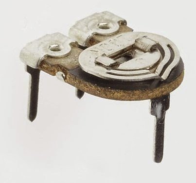
Presets are designed for PCB mounting applications, and can be soldered directly over the given PCB holes, unlike potentiometers which are required to be mounted on the enclosure of the unit with the help of a screw nut arrangement.
If you have more questions regarding potentiometer functioning details, please feel free to express the same through comment.


Questions & Answers
Can a “POT” used in 120 volts STROBOSCOPE be re-used to control a 12 volt motor ?
It can be used if the pot’s value matches the motor application.
Hi sir can a potentiometer work in reducing the volume of a digital radio which uses buttons ??
Hi Kevin, yes that’s possible. if the pot is positioned between the amplifier and the incoming audio signal.
Fine,
Tks
M
Hi, thank you very much for your beautiful work, plenty of interesting projects and ideas!
About potentiometers/trimmers: I’m a bit confused on how to connect a 20K trimpot to substitute a fixed resistor (10K) feeding the positive input of an opamp (LM358) in a signal-detecting power-on circuit. A picture would be great and better than thousand words…but I don’t know if is it possible to post images or links to the project
thanks
Marco
Hi, thanks for visiting this site, I am glad you liked it. I think you can simply follow the diagrams shown under the “2-pin, 1 way mode” heading.
The ends of the wires shown in these pictures can be replaced with the points of the 10k resistor.
Unfortunately there’s no direct image uploading facility here. But you can do through Google drive image file in the sharing mode. Mae sure to remove https while sharing the link.
Thank you Sir,
I appreciate your fast answer, I thik I understood, please have a look at the link
drive.google.com/file/d/1u_PKpzP-PfZKMWOObUG5wEWwrCvf4jZ0/view?usp=sharing
regards
M
Thank you Marco, That looks perfect to me.
Good info! Thank you.