In this article I have explained how to make a very simple circuit for buzzer using piezo electric transducer, two resistors, a small coil and a BC547 transistor.
A buzzer is a high frequency oscillator circuit used for generating a buzzing sound through a transducer or speaker output.
Simple Buzzer using a Single Transistor
Just a single transistor, a ferrite inductor, and a piezo transducer, that's all you will need to make this circuit “buzz” or rather “twit” for you, with an output that may be quite loud and ear piercing.
The simple piezo buzzer circuit described here actually works in a quite unique way. Instead of the normal working concept employed by other forms of oscillators which require resistor and capacitor networks for generating the oscillations, this circuit use inductive feedback for the required operations.
Circuit Description
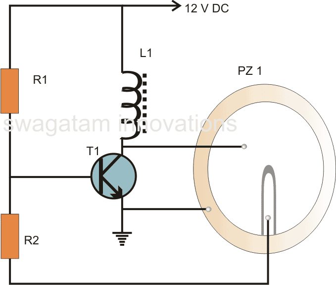
Referring to the above buzzer circuit diagram we find that the transistor T1 along with the inductor forms the heart of the circuit.
Basically the coil which is specifically called the buzzer coil, is in fact positioned for amplifying the created oscillations while the actual feed back is provided by the center tap of the three terminal piezo element used for the present application.
When a voltage is introduced in the circuit, the transistor conducts, operating the piezo element across the buzzer coil.
However this also leads to the grounding of the base of the transistor through the center tap of the piezo element, this instantly switches off the transistor and in turn the piezo also switches off, releasing the base of the transistor.
The transistor reverts to its original state and the cycle repeats, generating oscillations or the required “buzzing” frequency.
The center tap from the piezo transducer plays an important role in sustaining the oscillations and therefore in this particular design we need a three terminal piezo rather than a two terminal one.
The oscillations produced at the collector of the transistor is dumped into the coil, saturating the coil with magnetic inductions.
The coil kicks back the stored energy during the oscillations, magnifying the generated AC across it.
This stepped up AC is applied across the anode and the cathode of the piezo element, which starts vibrating sharply according the pitch of the frequency, generating a shrill, ear piercing sound in the air.
However to make the sound audible at maximum intensity, the piezo transducer needs to be glued or installed in a special way inside its housing.
Video Clip
How to Stick Piezo
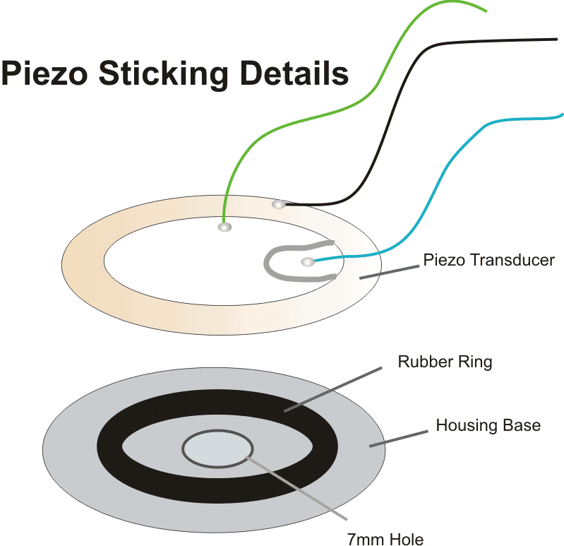
Video Clip showing the various procedures required for sticking a piezo transducer correctly:
For this particular application the piezo element needs to be stuck at the base of its housing which must consist of a hole having a diameter of about 7 mm.
The piezo element cannot be stuck directly over the base of the housing, rather it must stuck and positioned over a soft, pure rubber ring, having diameter 30 % less than that of the piezo transducer.
Only if the above fixing procedure is followed, the buzzer will sound, otherwise the sound may get choked and fail to reproduce.
Parts List
- R1 = 100K,
- R2 = 4k7,
- T1 = BC547,
- L1 = Buzzer inductor,
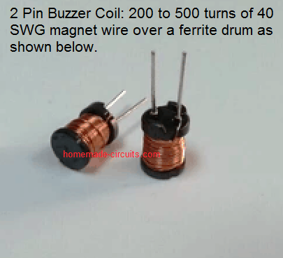
- PZ1 = Piezo element, 27mm, three terminal
- Rubber ring = 22mm
Formulas and Calculations
Transistor Operating Conditions
Base Current (IB):
IB = (Vin - VBE) / RB
Where:
- Vin = Input supply voltage
- VBE = Base-emitter voltage of the transistor (typically ~0.7V for BC547)
- RB = Base resistor value
Collector Current (IC):
IC = β * IB
Where:
- IC = Collector current
- β = Current gain of the transistor (typically ~100–200 for BC547)
Saturation Condition:
IB > IC / β
Inductive Reactance
Inductive Reactance (XL):
XL = 2 * π * f * L
Where:
- XL = Inductive reactance (in ohms)
- f = Oscillator frequency (in Hz)
- L = Inductance of the coil (in henries)
Piezo Capacitance and Impedance
Capacitive Reactance (XC):
XC = 1 / (2 * π * f * Cs)
Where:
- XC = Capacitive reactance (in ohms)
- f = Oscillator frequency (in Hz)
- Cs = Capacitance of the piezo (in farads)
Combined Impedance (Z):
Z = √((XL - XC)2 + R2)
Where:
- Z = Total impedance (in ohms)
- R = Equivalent resistance of the circuit (in ohms)
Power Delivered to the Piezo
Power (P):
P = VAC2 / Z
Where:
- P = Power delivered to the piezo (in watts)
- VAC = AC voltage across the piezo (in volts)
- Z = Impedance of the piezo (in ohms)
Energy in the Inductor
Energy (E):
E = 0.5 * L * I2
Where:
- E = Energy stored in the inductor (in joules)
- L = Inductance of the coil (in henries)
- I = Current through the inductor (in amperes)
Oscillation Frequency
Frequency (f):
f = 1 / (2 * π * √(Ltotal * Ctotal))
Where:
- f = Oscillation frequency (in Hz)
- Ltotal = Total inductance (internal + external) (in henries)
- Ctotal = Total capacitance (internal + external) (in farads)
Voltage Gain of the Oscillator
Voltage Gain (Av):
Av = XL / Z
Where:
- Av = Voltage gain (unitless)
- XL = Inductive reactance (in ohms)
- Z = Total impedance (in ohms)
Intermittent Piezo Buzzer Circuit using Transistors
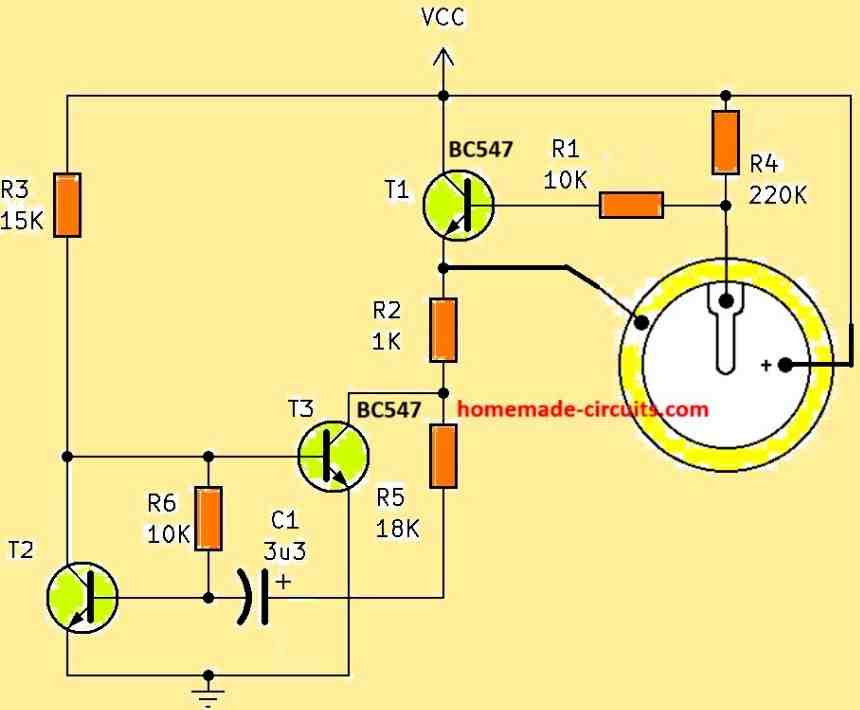
If you are looking for an intermittent piezo buzzer circuit that will produce a beep, beep, beep... kind of intermittent beeping sound, you can modify the above design in the following manner, to get this intermittent output.
Simple Buzzer using 8 Ohm Speaker
The circuit illustrated below generates sounds similar to a genuine buzzer. It simply works with two integrated circuits and very few parts.
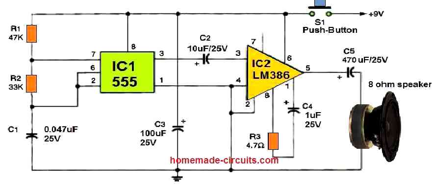
When S1 is temporarily pushed, C1 begins to charge via resistors R1 and R2. Pin 2 of the 555 oscillator/timer, IC1, is finally triggered. By driving pin#7 low, the IC begins to drain the capacitor via R2. This cycle will continue as long as S1 remains pushed.
The output of IC1 (pin 3) alternates in rhythm with the capacitor's charging and discharging, generating a sound frequency for IC2. IC2 is an LM386 low voltage audio power amplifier which amplifies the audio frequency's volume.
The speaker is employed to replicate IC1's tone frequency, that feels like a genuine buzzer sound. To get a low-frequency buzzing, you may want to increase the value of C1 to 0.1 uF.
For added stability, you can connect pin 7 of IC2 to ground through a 47 uF capacitor.


Discussion & Solutions
why do you need it? it's not necessary for such a simple design
the inductor value is 40mH wound over a ferrite drum
Thank you Chinmoy for your curiosity,
However I would repeat the same thing again…"why do you need it? it's not necessary for such a simple design"
I am afraid just like your other previous comments you once again failed to understand the core of the advise 🙂
I meant to say that we measure voltage and current parameters only for those circuits for which these matter, so that it helps the user to tweak and optimize the results from the circuit, and here it wasn't relevant at all since the circuit is heavily dependant on readymade components such as the piezo, transistor and the inductor, so it wasn't so important, it's just about using good quality components and witness perfect results.
And as far as a new learner is concerned it becomes even more meaningless and irrelevant for him to know these parameters, because a new learner must first learn the basics regarding transistors, piezos, inductors etc, and then learn how these need to be configured for achieving the intended results, there's no point in jumping to an oscillator and start measuring the voltages and current, what would the new learner understand from these data?
And by the way, piezos vary a lot for different makes and brands, and so does the hfe of the transistors and so does the mH of the inductors, which are procured readymade….so IMO these can definitely cause variations in the discussed parameters and there’s no way to change these until the components were itself changed,…and again it's not important to change these variations because it wouldn't yield anything substantial in terms of the sound intensity.
Sound intensity for the above design is hugely dependent on how it's stuck on the base, the quality of the rubber ring and the size of the hole of the front lid.
Hello, i wiuld like to buy a certain quantity of those pzt elements for a project i'm having.
The only problem is, i need to know much power output one piece can provide per pulse, and i don't know how to calculate it with the data dosplayed on the datasheets… can someone help me?
The datasheet reveals that it has a resonant impedance of 300 ohms approximately, so you can use is this with reference to the supply voltage and use Ohms law for calculating the current intake
Once you find the current you can multiply it back with the supply voltage.
"L1 = Buzzer inductor" in india where it i can get them in bulk please give the contact.
you can get it from Lamington Road, Mumbai
Please tell 12v piezo continues buzzer inductor coil full specifications
Sir please give me your contact number I want talk to u for i am stating new business to manufacture piezo buzzer.i want need your help sir.
sorry, I don't provide telephonic assistance, if you have any questions you can put them here.
the inductance value is around 40mH (milliHenry)
image can be seen here:
2.bp.blogspot.com/-8dkdn6B6OUc/VVBH_3imhcI/AAAAAAAAKLQ/3fKYTil2Fi4/s1600/buzzer%2Bcoil.png
Inductor coil & 27mm nickel buzzer plate How much cost in bulk for each peace
I don't know about the latest rates, you can inquire it in Lamington Road (Mumbai).
…by the way manufacturing the above explained buzzer won't be easy because plenty of small and big companies are already manufacturing these at extremely competitive rates……
HI.I AM WORKING ON PROJECT FOR BONE DENSITY MEASUREMENT USING PIEZO.I HAVE PIEZOELECTRIC DISC(500KHZ),PZT-52.CAN YO HELP ME IN DESIGNING THE ACTUATOR AND SENSOR PART
Hi, if you can provide more details regarding the concept then may be I can try.
i am suppose to measure bone density using piezo disc P-52,i want to make piezo to work as an actuator at one end(exciting it usinf electric field so that it produces at stress at one side) which is attachted to a bone.the waves will travel through the bone and are picked up by other piezo patch at other end.and correspondingly define conductance and thus bone density
you mean to say the bone density will causing variations in the frequency level from one to the other end? I don't think do this concept will help to measure bone?
I can design but that won't help the purpose…
sorry a lot of typos in the above comment, here's the corrected version:
"you mean to say the bone density will cause variations in the frequency level from one end to the other end of the bone? I don't think this concept will help to measure bone density?
I can design it but that won't help the purpose…"
resonant frequency:500khz,Electrical-mechanical Coupling coefficient:0.75±8%,Mechanical Quality Factor:60±15%, these are the specifications of my piezodisc
WE CAN DETERMINE CONDUCTANCE WITH RESPECT TO FREQUENCY AND HEREBY DETERMINE THE DENSITY
How can I change the buzzer inductor. By mistake my younger brother used it with main current electricity.
hi sir,
good afternoon
please watch video (https://www.youtube.com/watch?v=FgcB7Lkvp44)
i want to generate same sound effect using electronic circuit ,
do you have any idea,
i have single pulse by which i want to generate the same sound effect.
Thanks
Nikhil
Hi Nikhil, It's a TINGGGGG sound…sorry I don't have it… it needs to be programmed or designed and tested with a lot of trial and error
Hi sir ,i have a piezo (black) which gives beep when applied to 3v…i want to make sparrow sound through it using 220v capacitive power supply
sorry, I am not sure about this circuit idea
Hi All,
Perhaps it not the right post to ask my question but if you can help me it would be great. I am trying to generate small voltage (~5mV) from sound of high frequency (~20 Khz). Also I need a cheap option to make it (~ INR 5) as I would require to mass produce the circuit. I was thinking of using a piezoelectric in place electromagnetic inducers for the same. Do you think it is possible
Hi, a piezo can be tried, but only if the sound pressure (volume) is reasonably good.
Can you help with the circuit. I cant seem to generate a sustainable voltage.
please specify the volume level of the source, and at how much distance the sensor would be allowed to be positioned….
HI Swagatam!
Just curious… can the BJT be replaced with an AO3400? What effect will it have on the circuit? I was hacking a 3-24V piezo and I think I blew the L6 transistor. The L6 is a 200-400 hfe SMD NPN transistor. I don’t have anything like that, but I do have the AO3400. Its really not a big deal as I have plenty more of the same piezo buzzers. I was just curious. Thanks!
Hi Norman, yes it might work, if the supply is above 6V
I want to design buzzer but i have to create time delay for ON/OFF of 2 sec using passive component and using one DC supply of 12V DC no addition switching supply can not be used.
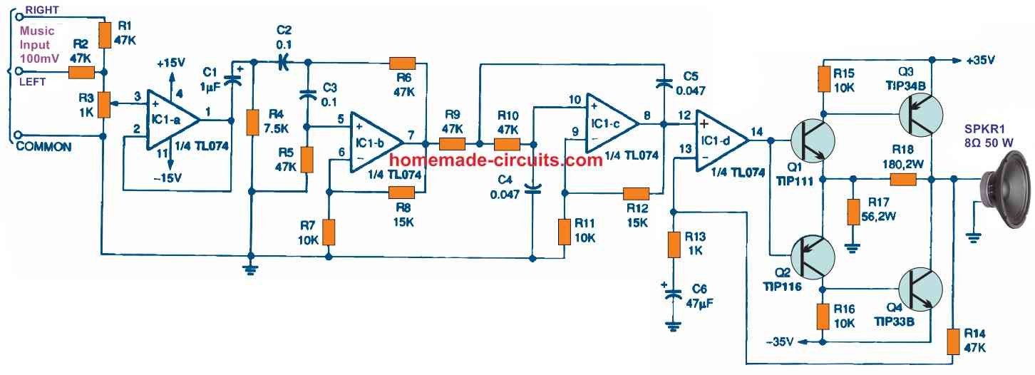
You can connect the above buzer across the output of the following circit:
Make sure to increase the C1 value to 1uF
Hello Sir,
What should I have for the value of R1, R2, L1 if I have access a dc voltage of 5.5VDC? Thanks!
Hello Alex, you can use the same set up for 5V operation also…
Hello Sir,
I have a current limit of max 1 mA. Wondering if you have any suggestions? Is it possible to decrease the period of the tone with a simple modification on your Simple Buzzer circuit? Thanks!
Alex, the above circuit cannot be customized for frequency, you can try the following instead:
https://www.homemade-circuits.com/simplest-piezo-driver-circuit-explained/
Design a variable frequency oscillator using Electric Bridge network to employed as actuating signal for a buzzer circuit indicating over-current in the system. Assume suitable frequency range for buzzer and electrical load. Justify the selection of the components.
Hi Swagatam,
thank you for sharing your ideas and inventions for us, like me, that is just a hobbyist interested only in understanding new things.
Please, could you explain to us… Is this circuit the same used to prank with small shocks when touched by removing the piezo part?
Tnx a million!
You are welcome Henrique, The coil can be used for generating high voltages enough to jolt anybody with a tiny shock, but the above circuit cannot be used for that purpose without the piezo transducer. Because without the piezo the circuit will not oscillate. If you use any other form of oscillator with this inductor then probably it can be used for the mentioned application
Thank you so much again for your very kind and quick reply 🙂
I am learning w/ you because I am teaching few kids helping them to forget TV, video games learning something useful… but I know nothing!
I am just transferring/translating what you teach.
Is it possible to create a wireless control that could send signals to the buzzer making it to beep like telegraph helping kids learn Morse code with fun?
If so, would you mind teaching us how to do it?
Thank you so much again !!!
No problem, I am glad to help!
To make a wireless morse code circuit, there are 3 things you will have to learn to build. 1) the code oscillator circuit, 2) the Transmitter circuit, 3) the receiver circuit, which can be a small FM radio.
You can start with the oscillator circuit first, as given below, if you succeed then we can move to the transmitter circuit:
The crystal earphone can be replaced with any normal head phone
Thank you Swagatan,
We will do Telegraph next weekend, the kids are getting mad…
all of them asked to make the shock first.
But I am learning to teach… and I didn`t understand well..
What should we connect after Piezo part to create shock w/ small batteries AAA or Lr44 ones? I am scared to use 9Volts batteries.
Thank you again
No problem Henrique.
After making the buzzer circuit successfully, try touching the two ends of the coil, you should find some shock like vibration.
The mosquito bat circuit is one good source of converting 3V to 1000 V shock
Hi Swagatam,
I understood, it will arouse curiosity among all kids making them willing to learn. 🙂
Thank you so much, I have to travel to work, but after returning I will show what we have done as we recycling parts instead buying, and this makes a bit more difficult but will work, I hope.
Thank you again
No problem Henrique! wish you all the best!
Hi, I have a simple piezo transducer with only 2 leads . How can I substitute as a 3 lead?
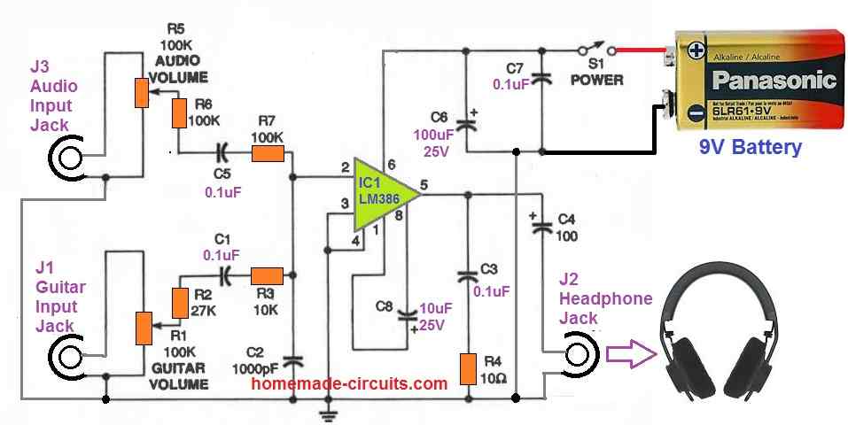
Hi, you can try this circuit:
replace the speaker with your piezo, and also add a suitable inductor across the piezo wires
Hi. I have just discovered your site; it is very interesting and useful to complete electronic newbies like me. I have made the basic buzzer circuit (https://www.homemade-circuits.com/how-to-make-simple-piezo-buzzer-circuit/) and fiddled with it, trying to change the pitch of the output. Nothing changes it. I have thought about this and wonder if it is because the feedback part of the piezo ‘speaker’ fixes the output frequency. Is that the case or is there something else going on? Do you have any circuits on the site that I haven’t found that show how the pitch of a piezo ‘speaker’ can be changed?
Hi, thanks for liking this site! you cannot adjust the tone frequency of the sound in this circuit. yes it is due to the feedback element determining the frequency
you can try the following concept instead for a variable feature:
Simplest Piezo Driver Circuit Explained
Thank you; I will certainly try that (with a 2-terminal transducer…)