A cellphone or mobile phone detector is actually a high gain op amp amplifier which detects slightest of RF disturbance from a mobile phone, and illuminates an LED.
Mobile phones today being the major generator of RF interference is easily picked up by this circuit and can be seen through an LED illumination at the output of the circuit.
Working Concept
The concept behind the working of this simple mobile phone detector is a highly sensitive comparator circuit which is unstable at its input due to high sensitivity, such that it turns ON even with the minutest electrical interference in the atmosphere around it.
Since it is designed to detect mobile phone signals one may misinterpret it to be detecting the GHz signals, actually it's not, and it simply can't.
Even if the mobile phone signals may be oscillating at GHz levels, the signal is still a radio frequency (RF), having the properties of electrical interference.
It is this electrical interference that is picked up by the op amp input, and converted into a DC output, for illuminating the LED.
Basic Design Using a Single IC 741 Op-Amp
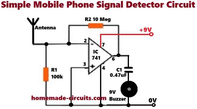
Parts List (BOM)
- Resistors are 1/4 watt CFR 5%
- 100k = 1
- 10M = 1
- Capacitor 0.47uF ceramic Disc = 1
- IC 741 or any standard op-amp = 1
- 9V piezo buzzer = 1
- 9V PP3 Battery = 1
Referring to the above circuit diagram, the working of the basic mobile phone signal detector can be understood through the following description:
Signal Detection
Here is how it all works, When a mobile phone is in action, whether it is making calls, receiving them, or sending texts, it sends out those RF signals.
The antenna catches these signals and sends them right into the op-amp’s inverting input.
Signal Amplification
Once detected, this weak RF signal gets amplified by the op-amp (the IC 741) thanks to its high feedback resistance from R2 and its own high gain.
The result? An amplified signal that is strong enough to get our buzzer buzzing!
Noise Filtering
Meanwhile the Capacitor C1 steps in to filter out any annoying noise or low-frequency bits from that amplified signal.
This way we ensure that our buzzer only reacts to real RF signals coming from mobile phones.
Buzzer Activation
Finally when an RF signal gets detected and amplified enough the buzzer receives just enough current to spring into action.
It then produces an audible tone letting us know there is some RF activity happening nearby.
Formulas and Calculations
Gain of the Op-Amp
The op-amp IC 741 is used in an open-loop configuration meaning its gain is determined by its internal characteristics.
Open-loop gain (AOL):
The typical open-loop gain of a 741 op-amp is approximately 100000 to 200000 (100 dB).
Formula:
Vout = AOL * (V+ - V-)Where:
- Vout = Output voltage of the op-amp
- V+ = Non-inverting input voltage (connected to 0V or ground)
- V- = Inverting input voltage (signal from the antenna)
Since this circuit does not include external gain-setting resistors the op-amp operates with its maximum open-loop gain.
Impedance Considerations
The antenna and the resistors R1 and R2 form a voltage divider for the input signal. The impedance of R1 and R2 affects the sensitivity of the circuit.
Input impedance:
The input impedance (Zin) at the inverting terminal of the op-amp is primarily determined by R2 which is 10 MOhm. This high input impedance ensures minimal loading on the antenna signal.
RC Filtering
The capacitor C1 (0.47 uF) acts as a high-pass filter to block DC and low-frequency signals.
High-pass filter cutoff frequency (fc):
The cutoff frequency is determined by the op-amp output impedance and the capacitor:
fc = 1 / (2 * π * R * C)But as the op-amp output impedance is very low, R can be neglected. For practical purposes the circuit passes signals in the RF range (MHz to GHz).
Current Through the Buzzer
The buzzer operates when sufficient current flows through it. Assuming the output voltage from the op-amp is near saturation (close to 9V):
Current through the buzzer (I):
I = V / Rb- Where:
- V = Output voltage from the op-amp (approximately 9V)
- Rb = Internal resistance of the buzzer (typically around 100 Ohms)
Signal Sensitivity
The smallest signal (Vin) detectable by the circuit is determined by the op-amp's input offset voltage (Vos, typically around 1 mV) and the gain:
Vmin = Vos / AOLFor a gain of 100,000:
Vmin = 10 uVThis is sufficient to detect weak RF signals from a mobile phone.
Design Validation
To confirm the circuit works as intended:
Verify that the op-amp output saturates to near 9V when RF signals are detected.
Ensure that the antenna captures RF frequencies, so you can use simple whip antenna (wire of length around 6 cm) is suitable for GSM frequencies (900 MHz to 1.8 GHz).
Increasing Sensitivity using 4 Op-Amps (LM324)
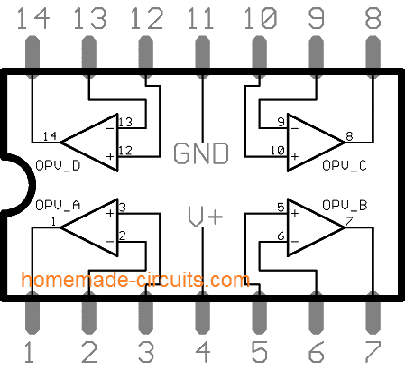
This circuit is basically a simple high gain inverting amplifier, built around the IC LM 324. Only two of its op amps may be incorporated, however for making the circuit extremely sensitive, all four of its opamps have been rigged in series.
Looking at the figure we see actually the the circuit is a repetition of four identical circuits in series.
So we would only want to study the basic concept of the any one of the stages consisting just one op amp.
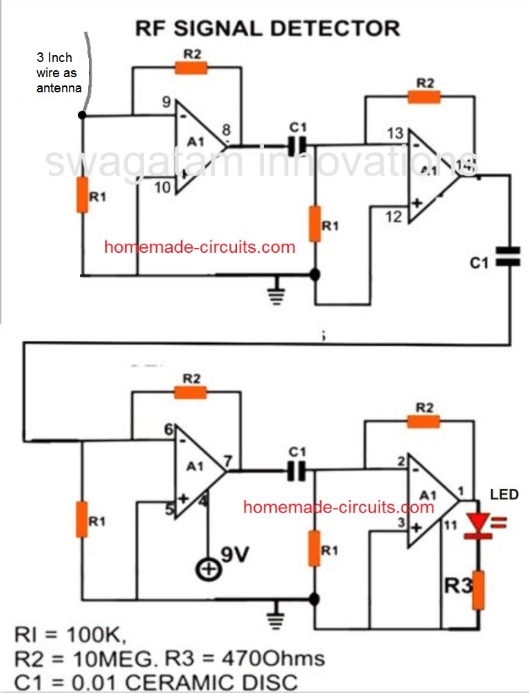
NOTE: Using 4 op amp stages can make the design extremely sensitive and the circuit may start sensing all sorts of RF signal that may be present in the atmosphere. Therefore I recommend using only 2 op amp stages in series for this project.
Parts List
- All R1 = 100K 1/4 watt
- All R2 = 2.2 Meg or any value between 1 Meg and 10 Meg (1/4 watt)
- All C1 = 0.01uF, or 103 ceramic disc or PPC, any type will do.
- A1 --- A4 = LM324 IC
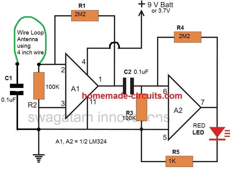
As mentioned in the earlier part of this article, the op amp is configured as a high gain non inverting amplifier, where the input is received at the pin #2 which is the inverting input of the op amp.
The RF disturbances in the air is received by the antenna and fed to the inverting input of the op amp which is amplified by the circuit to some specified level depending on the value of the feed back resistor across the output and the inverting input of the op amp.
Increasing the value of this resistor increases the sensitivity of the circuit, however too much sensitivity can make the circuit unstable and induce oscillations.
The amplified signal is fed to the input of the next stage which is just a replica of the previous stage.
Why it is so Sensitive
It's due to the 4 series op amp stages which helps to make the circuit highly sensitive an this can pick up cellphone RF from a distance of 10 meters.
Here the relatively weaker signals from the first stage is further enhanced and made stronger so that now it may be fed to the third stage for repeating the actions that is for further amplification until the last stage whose output illuminate an LED, displaying the presence of even the minutest possible RF disturbance in the air.
UPDATE:
After a lot of experimentation I finally realized that creating a long range cell phone detector wasn't feasible. It's because the modern phones have a high grade RF shielding, which allows only very little RF to leak out from the phone. Therefore the RF do not reach too far in the atmosphere making it impossible to detect them beyond a few inches from the phone.
To improve the distance I tried making the circuit more sensitive by adding more stages in series, but that didn't work. Because higher sensitivity meant the circuit started detecting many different existing RF disturbances in the air, which kept the LED flickering all the time.
Video Demo
The Finalized Circuit
The finalized tested design can be seen below, it is exactly similar to a WiFi detector circuit
How to Assemble the Circuit
The discussed circuit of cell phone RF signal detector, sensor is very easy to build and requires minimal knowledge of electronic for going about with the procedures. It is built with the following instruction:
After procuring the given components, fix them over the piece of general PCB in the following manner:
Take the IC first, and carefully insert its legs inside the PCB holes through proper alignment.
Solder the leads of the IC.
Now as per the diagram start connecting the resistors and capacitors one by one to the pin outs of the IC, remember that from the component side of the PCB, the pin out will be just the opposite to what it is from the track side, so be careful with the pin out designations and connections.
How to Test
Once it is assembled, it’s all about connecting the board to a 9 volt battery and confirming the results.
For this you may make a call from your cell phone or just call to know your balance report, the LED in the circuit should hopefully start responding to the cell phones generated RF signals.
Alternatively, you may try clicking your kitchen gas lighter very close to the antenna of the circuit; the LED could be seen flashing with the clickings of the gas lighter.
Another way of checking the circuit would be to take it near your mains electric board, the LED should light up when brought even withing a feet near to the board indicating the presence of the mains field and confirming the working of the circuit.
Note: The coil L1 can be made from any gauge wire, just a few turns of any diameter between 5 to 9mm will do.
RF Sniffer using a Single Op Amp
While the RF mobile detector circuit was primarily meant to indicate the existence of RF emissions, this circuit is implemented for several different functions, such as testing car security keys and as a bug detector.
The RF sniffer circuit is so sensitive that it can pick up fields as low as to 1 mW at 1 m distance and from around 100 kHz to 500 MHz signals.
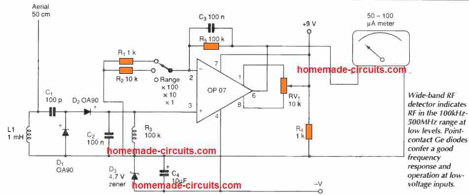
Essentially, it is just a broad -band input circuit, a rectifier and meter, nevertheless for achieving required sensitivity an amplifier is necessary and the diodes should be accurately selected.
Germanium diodes are able to operate even at lower forward voltages compared to the silicon types, and frequency response is bigger using point contact devices, therefore point -contact, germanium 0A90 diodes happen to be the best alternative.
A 1 mH inductor over the input minimizes LF sensitivity, as does the feedback capacitor. Adjusting the meter offset is not important, nonetheless it will enable the nulling of unwanted frequencies.
The meter might require series resistance to fine-tune sensitivity. The display reading may not be linear and will only help to indicate the presence of RF and the relative power of the RF.
Mobile Phone Detector Circuit with Relay
The next mobile detector circuit will not only indicate the mobile RF through an LED, it will also activate a Relay for controlling a desired external load. Thus, this design includes an LED indicator as well as a relay for powering an external load in response to a detected mobile RF signal.
Simply operating a mobile phone near an audio device gives an idea of the strength of the electromagnetic disturbances that a mobile phone is capable of creating.
The strong buzzing at 217 Hz that often occurs is a direct consequence of the communication mode used by the GSM system: short bursts of powerful pulses at 900 or 1800 MHz, repeated at a rate of 4.616 milliseconds. This allows different communications to "pass" simultaneously on the same radio frequency.
The mobile phone does not only emit signals during an active call.
Even in "standby" mode, it periodically responds to network requests so that the network can constantly locate and authenticate it (for better or worse...).
More substantial data exchanges occur when the device is powered on, as well as when it receives a call or a text message (SMS).
Before receiving a call or data, the mobile phone needs to confirm with the network that it is capable of doing so. It is the transmission of this confirmation message that is detected by all standalone "vibrators" sold as accessories, which is why they activate even before the phone rings.
Our circuit operates on the same principle and will therefore react in a very similar way.
The Preamplifier:
To detect the pulse trains emitted by the mobile phone, an approach was conceived to exploit the strong disturbances experienced by audio equipment in the immediate vicinity of operating mobile phones.
It should be noted that with a typical power of 2W (at 900 MHz) or 1W (at 1800 MHz), the mobile phone emits a significant pulsed electromagnetic field in its immediate surroundings.
Some studies suggest that in order to present no risk to health, the phone should be kept at least... twelve meters away from the ear!
At a distance of a few tens of centimeters, the field is sufficient to induce tens or hundreds of millivolts at the terminals of a roughly tuned antenna (for example, a simple unshielded wire, 2, 4, or 8 cm long).
If this conductor is connected to a component acting as a diode, it can capture UHF bursts that reappear as audible impulses. This can cause interference and render amplification ineffective.
In a preamplifier circuit, for example, a rigorous design in terms of electromagnetic compatibility (EMC) allows contemporary (high-quality) products to have an acceptable level of immunity.
Unfortunately, the same cannot be said for older equipment, even if they are still in perfect working condition, and of course, for many low-end devices.
The mobile phone detector circuit diagram in Figure 1 below, relies on a purposely "poor" preamplifier stage, built around a common operational amplifier (half of an LM358).
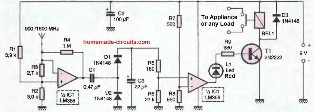
The significant gain and the input configuration deliberately place it in conditions that make it susceptible to electromagnetic disturbances.
The numerous internal junctions of the integrated circuit are responsible for the actual detection of radio impulses, while the discrete component "doubler" voltage rectifier integrates their envelope in a rather smooth manner.
How the Circuit Works
During each detected UHF impulse, the 22 uF capacitor charges a little more through a 180-ohm resistor. However, during the resting periods between impulses, it discharges slowly through a 27 k-ohm resistor.
It is at this level that the choice of values for the RC components allows for the desired triggering selectivity.
The adopted ratio between the charging and discharging time constants, for example, makes the circuit insensitive to the short data bursts periodically emitted by the mobile phone for identification, even though these bursts can be detected with an oscilloscope at the output of the first operational amplifier.
The much longer data block transmitted just before the phone accepts an incoming call (even if the ringtone is deactivated) is sufficient to charge the capacitor to a level that triggers the comparator (second half of the LM358).
Therefore, a simple transistor is enough to activate a small relay and simultaneously light up an indicator LED.
More ambitious projects could involve a microcontroller to analyze the impulse frequency detected by the first operational amplifier more precisely, potentially preceded by a high-gain UHF amplifier.
This principle is used in mobile phone detectors, particularly by security services, which need to be much more sensitive and free from false alarms.
Construction
Although designed to exploit signals at the limit of microwave frequencies, the circuit uses a perfectly conventional wiring technique.
The printed circuit board in Figure 2 is designed exactly like any other audio preamplifier, except that the most basic rules of electromagnetic compatibility (EMC) have been blissfully ignored.
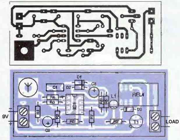
As a result, it is more susceptible to GSM interference, which can be further increased by adding a tuned antenna.
A large center pad allows for direct mounting, perpendicular to the printed circuit board, of a replacement antenna for a mobile phone, but a rigid wire of 4 or 8 cm can work just as well (it's ultimately a matter of aesthetics).
The wiring of the remaining components, according to the layout in the figure above, does not require any particular comments, except that it is strongly recommended to use screw terminals for the connection of the relay contact to its user circuit and for the 9 to 12V power supply (typically a miniature battery).
How to Use
The circuit does not require any connection to the mobile phone since it operates purely through induction.
In principle, triggering is possible up to a distance of 50cm, or even a meter when the mobile phone is using its maximum transmission power.
It should be noted that mobile phones constantly adjust their transmission power to the minimum level necessary for a good connection with the base station.
In areas with excellent coverage, the power can be significantly reduced, which also increases the battery life.
As a result, the ring relay (or any standalone vibrator) may appear less sensitive. To ensure optimal triggering reliability, the closer the distance, the better.
With a standby power consumption of around a milliampere, the circuit can operate for a long time with a simple 9V battery, but it can also be powered by a vehicle's battery.
In such cases, care should be taken not to exceed the current rating of the relay used (for example, using a "special automotive" relay to control a high-power consumer such as a horn).
In many cases of permanent fixed operation, a mains power supply can be used, provided it is carefully filtered and stabilized due to the device's high sensitivity.
It should be noted that the circuit is capable of detecting other pulsed RF fields emitted by devices other than mobile phones.
It will trigger, for example, when brought close to the door of a functioning microwave oven, even if it is sealed.
This type of observation helps to some extent in clarifying concerns about the health effects of mobile phone use.
It has been suggested that twenty minutes of uninterrupted use would cause a local increase of one degree in brain temperature!
It seems that the radiation experienced is of the same order of magnitude as that which would be received from contact with the door of a certain type of oven for the same duration, which is generally recommended to be avoided when it is operating...
On the other hand, one can often find reassurance regarding the potential harmfulness of fixed station antennas that are scattered everywhere.
Outside their main emission lobe (i.e., right in front, where apparent powers of several hundred watts are common), the circuit generally needs to be brought very close to trigger a response.
It seems that being near or behind fixed station antennas is much less harmful than regularly and extensively using a mobile phone...
Perhaps this little circuit will inspire some of our readers to further explore the subject.




Questions & Answers
does the antenna need resonator to select a particular frequency
The circuit will detect all kinds of frequencies coming under the RF range, and does not have the capability of detecting particular frequencies. Antenna is an ordinary wire length.
can we inductor in place of L1 coil….and if we can use inductor then what should be the value of inductor.?
can we use inductor in place of coil L1… and what should be the value of inductor?
yes it can be used…
What is the properties of L1?
Do you have cell phone signal booster ?
inside of my flat signal is not available so is this possible to boost signal from outside and give it to room using antenna and booster ?
please provide booster circuit
can you give GSM signal booster circuit ?
inside of my flat i dont get signal for any provider but outside i am getting full signal so now i want to get signal from outside using antenna and boost it and spread it inside of my flat
I am sorry, I do not have it presently.
but is this possible to develop the circuit own ?
are they available in the market, and do they really work?
Hi Shadrach,
It looks to be a very complex and sophisticated circuit, it could be impossible for an ordinary hobbyists like us to build it at home, no chance according to me.
hi sir!!! long time no chat.
Can you give a specific coil L1, the coil with the longest range to detect?
short it with a wire link…..
What is the size of the capacitors? I used 0.01 (micro Farad) and it is not working.
the capacitor value is not so critical any other value will also work if you have done everything correctly.
to confirm you can take the circuit near the mains socket or wiring, the LED should begin glowing
Good morning, i would like to know if i can add a gsm module to the circuit which when a RF signal(cell phone) is detected, the gsm module send a message to a dedicated person
yes it's possible first you will have to buy a GSM module, set it up and then configure it with the above described RF detector for the intended actions
thanks for the answer… but can i make the circuit detect only cell phones by adding for example bandpass filter?
the above circuit triggers by sensing RF current not RF frequency so what you are referring to may not be feasible…
Sorry sir, is it possible not using L1. Will the circuit work??
L1 is just a wire link from C1 to ground….
Swagatam.. first of all a salute to u… ua blog has helped me a lot…. i want a simple mobile
network jammer… plz
aqib, you can try the concept given here:
https://www.homemade-circuits.com/2014/11/rf-signal-jammer-circuit.html
however the coil will need to be experimented so that it covers the 1Ghz range… the coil will need to be replaced with a few mm length silver coated wires
also all the parts will need to be made SMD and very close to each other
Hello Sir.
How are you? Its been a long time since the last time we communicate. I've been busy lately. Do you still remember our wireless helmet brake light project? Finally it was a success! Thank you so much Sir for your patience in teaching me. But I made several modifications. I finally got myself a wireless doorbell that has a 12V Tx. So no problem anymore with the voltage requirement of the Tx. It works flawlessly. I will send you some pictures next time.
By the way, as always, I have an inquiry again. Are you familiar with the 1SS99 diode? I am having a hard time finding it. Can you suggest any replacement for it? Thank you so much. Your input will be highly appreciated. Have a good day Sir.
Hello Bugoy,
Welcome back, Yes I very much remember our wireless helmet project. I am glad to know that you could finish the project successfully.
Do send me the pictures so that I can post them all under the relevant article.
the diode is a UHF ultra fast Schottky diode, you can try ND4991 or NTE112 or BAS40 as equivalents.
Hello Sir!
I am so happy with the wireless helmet brake light. It was really a beneficial gadget for any rider like me. It increases visibility especially during slow-moving traffic wherein the driver behind a motorcycle cannot see the actual brake light due to its low position.
Unfortunately Sir, the ND4991 and NTE112 were as well not available here. What can you say about the 1S1925?
Thank you Sir again. You are no doubt heaven sent.
Thanks for the update Bugoy,
Can you specify where exactly do you intend to use this diode?
I think you should try a 1N4148 instead it's pretty fast too, and might just work for you.
Good Day Sir!
I saw a schematic diagram on the internet about a microwave motion detector. I am interested to make it. But when I inquired the parts here at our local stores, they don't have some of the parts. Do you remember also our first project? That turned out to be not functioning as it should be? The capacitive proximity sensor. Wherein I needed to have an isolated power supply for it because the motorcycle's body/chassis ground is affecting its performance if hooked up directly to the battery. But when we're done with the isolated power supply circuit, it still don't work. So I am now into microwave sensor. I really want to protect my motorcycle Sir. I don't have trust on aftermarket alarm systems because they employ shock sensor which is so easy to fool. I want an alarm sensor that senses someone who approaches the motorcycle from a short distance without actually touching the motorcycle.
Thank you so much Sir.
Good day Bugoy, yes I remember the project, it was discussed under the "capacitive touch sensor circuit" article.
I will do some research and try to get more info regarding the microwave sensor circuit concept
I'll come back to you and discuss more once I find something interesting.
Hello Sir!
Good Morning.
I just found out another problem that I would encounter if ever I will continue the proposed project. I noticed an etched pcb trace on the pcb design that acts as an inductor. I'm guessing it was specifically design for the particular circuit. I am sure I cannot make that exact design using only permanent marker pen as masking agent for pcb fabrication.
Do you know any other means to detect a intruder without any physical contact? Or maybe a touch sensor that could handle large volume and surface area such as a motorcycle body.
Thank you so much Sir.
Hello Bugoy,
I think you can try any ordinary motion detector circuit for protecting your vehicle, simply install it with it's sensors near the speedometer and pointing towards the seat and its range not beyond the tail of the motorcycle, this will ensure that the alarm only sounds when somebody tries to actually ride or touch the vehicle.
once design can be seen here:
https://www.homemade-circuits.com/2013/10/accurate-infrared-motion-detector-or.html
Hello Sir!
The idea of an infrared sensor is quite good but it is only directed towards a limited area in the motorcycle and protects only a straight line. What if the thief would crouch and start dismantling the wheel? It is rampant here in the Philippines the theft of wheels or other parts of a motorcycle. The thieves don't get the whole motorcycle but only parts easily dismantled, like side mirrors, wheels, cdi, lights, etc. So I would like to have an exceptional alarm sensor that catches thieves before they do any harm on my precious property.
Thank you so much Sir.
yes that's correct…let's look for other options
Hello Sir!
Have you seen the circuit diagram of the microwave proximity motion sensor that I am planning to make? I have a question though. Is it possible to replace the etched pcb strip line with an air core inductor? If yes, what gauge of copper wire and how many turns and core diameter?
Thank you so much Sir. I really want to do this project. Also, do you have any idea what is inside those aftermarket proximity sensor that I referred you to?
Hello Bugoy, yes I have seen it, you can simply use a 1 cm long 1mm thick copper wire in its place.
this much length is more than enough since we are dealing with frequencies over 1GHz
I have not researched all the links yet, I'll try to do it soon and let you know as soon as I have something interesting to share
Hello Sir!
I got worried about you. I just learned that a strong earthquake hit Nepal and parts of India. How are you Sir?
Thank you for your concern Bugoy, fortunately there hasn't been any tremor in the part of the country where I live (Mumbai), so I am very much safe, no problems.
Thanks very much!
Hello Sir!
How are you?
Hello Bugoy, I am fine, I'm still busy with my site optimization issues, I remember your request regarding the microwave sensor, and I'll surely look into it as soon as I become free….
Hello Sir!
Why did your website goes back to original? Anyway, I have some news for you. I tried the circuit, I used 1S1925 instead of 1SS99 and 2N7000 instead of BS170. I also used 1cm copper wire as inductor. Some things happened. It detects movement and lights up the LED but it mistriggers everytime. The LED blinks erratically. Not stable. Why is that Sir? How can I make it stable? Thank you so much.
Hello Bugoy, the new website was full of bugs and very difficult to manage therefore I decided to switch back here.
As for your microwave circuit, that's a great news, you could get it to work at the first instant looks impressing.
The erratic behavior could be because of a badly configured antenna stage.
Since the system uses a GHz range, the sensitivity of the antenna stage could be very high and critical, all the parts here must be placed as close as possible to each other and the soldering should be of a very good quality with all flux residues removed and cleaned.
Also the PCB must have all the tracks surrounded with the ground tracks, or simply place the entire assembly over a metal plate and connect all the negative points of the circuit with the metal base.
The erratic behavior could be due to self oscillation and instability.
The above modifications can possibly help reduce the above issue.
Bugoy, I'll check those links, but no matter how to take care, there's no way to identify whether the circuit is actually working or not as per the specs and this can make things very difficult to verify.
That's the reason I suggested you to use a microwave sensor module which can make the proceedings much easier and give guaranteed results, I have published one article here, youj can check it out here
https://www.homemade-circuits.com/2015/05/ghz-microwave-radar-sensor-alarm-circuit.html
sorry about the typo, I meant ………."no matter how much you take care"
Hello Sir…
Thank you for your input. But unfortunately, there is no more room for another battery in the motorcycle. That is the simplest, yet the biggest problem now. It worked flawlessly before when I tried to power it up with a car battery and connected the sensor to any metal part of the motorcycle. But when I tried powering it up with 8 AAA Ni-MH batteries, it wont work Sir. I guess the circuit need more amps to compensate for the large surface area of the motorcycle. The 8 AAA Ni-MH batteries only works for small surface areas like the wheel or the gas tank, but not the whole motorcycle.
Thank you again Sir.
Hello Bugoy,
If you are thinking that to sense a large surface area the circuit will require higher current, then your assumption may be wrong.
you can check the circuit again using the car battery and an ammeter connected in series with the circuit, you will find the current to be in 10 to 15 mA only without relay.
you can do one thing, operate the circuit with the AAA cells and operate the relay with the motorcycle battery….for this you will have to just isolate the relay driver transistor positive and the relay negative supply from the circuit and connect these with the bike battery.
Hello Sir!
Thank you so much again for your inputs. Well, for the meantime, I made the 8 million gain circuit that I saw in one of your articles. I use it to detect energized electrical lines. It works perfectly and I am happy with the result. The front is a piece of copper clad pcb as the sensor. Below are the link for some of the pictures:
i1284.photobucket.com/albums/a561/butchmillo/2015-05-15-1876_zps0dszjcdt.jpg
i1284.photobucket.com/albums/a561/butchmillo/2015-05-15-1877_zpsjaqzcyoa.jpg
i1284.photobucket.com/albums/a561/butchmillo/2015-05-15-1878_zpsdzzdya8f.jpg
Thank you for your unending patience with me Sir.
Thank you Bugoy, you are most welcome.
by the way can you provide the link of that article, I am unable to trace it out?
Sir,
Regarding your statement "you can do one thing, operate the circuit with the AAA cells and operate the relay with the motorcycle battery….for this you will have to just isolate the relay driver transistor positive and the relay negative supply from the circuit and connect these with the bike battery.", How will I actually do this Sir? I am a bit confused. Can you please provide me with a diagram? Thank you.
Bugoy, I'll surely try to provide you with a diagram but I am sure you would be able to do it by yourself by using an optocoupler.
It's just about isolating the relay driver stage from the sensor circuit using an opto coupler.
the LED of the opt can be connected with the sensor IC output, and the phototransistor output with the relay driver stage, once this is done the relay driver stage can be separately powered from the motor bike battery…the circuit side can now happily work using the AAA battery
Hello Sir!
Good day!
Thank you again Sir. I guess I may not be able to accomplish such task because there is no available optocoupler here Sir. Is there an alternative circuit to diy an optocoupler set-up? Also, what I did yesterday was to remove the relay and driving transistor from my circuit, but unfortunately, still it does not respond when used in the motorcycle. I cannot set the sensitivity. the circuit behaves either totally ON (when clockwise) or totally OFF (counterclockwise). There is no particular spot in the potentiometer where it should function as it should be. But when I try to use it on smaller objects like window grills, it works.
Thank you so much Sir.
Hello Bugoy,
I am sure that opto coupler will be available in your area too because optos are used in all SMPS adapters which have today become so common in the market.
or if you have an old mobile charger or an AC/DC smps adapter you can salvage it from there also, it will be like a small 4 pin IC.
once you get it you can wire it with your capacitive sensor circuit with the help of the following article images:
https://www.homemade-circuits.com/2013/02/how-to-drive-relay-through-opto-coupler.html
OK got it, thanks Bugoy, I appreciate your efforts
Hello Sir!
How are you? I just want to reiterate my statement from my previous reply. "Also, what I did yesterday was to remove the relay and driving transistor from my circuit, but unfortunately, still it does not respond when used in the motorcycle. I cannot set the sensitivity. the circuit behaves either totally ON (when clockwise) or totally OFF (counterclockwise). There is no particular spot in the potentiometer where it should function as it should be. But when I try to use it on smaller objects like window grills, it works." That means, even without the relay part of the circuit, it still does not work on the motorcycle.
Thank you Sir.
Hello Bugoy,
i think you are getting confused.
earlier you said that the problem was regarding using the motorcycle body as the sensor and also as the common ground with the circuit.
For solving this issue I suggested the optocoupler method which would allow the vehicle body to be used as the capacitive sensor and also allow the motorcycle battery to be used for operating the relay.
only the circuit section may be powered with a few AAA batteries, so this keeps the circuit stage completely aloof from the relay stage.
you cannot isolate the relay driver stage without making the ground or the positive of the circuit in common with the bike's battery, so your previous attempt might be incorrect.
it can be done only with an optocoupler.
…yes an LED/LDR can be also used for making an opto coupler, I have already discussed it through many of the posts, you can learn the building procedure here:
https://www.homemade-circuits.com/2011/12/how-to-build-simple-electronic.html
Hello Sir!
What I mean was, when using AAA batteries, the circuit can only cater to objects smaller than a motorcycle. In order for the circuit to function properly on a motorcycle, I use a car battery instead. So what I am asking now Sir is, is there a way to tweak or modify the circuit so that it can accommodate the whole motorcycle as the sensor? What components can I change? Resistors, capacitors, trimmers? No matter how I adjust the trimmer, still it wont function when used in the motorcycle frame. Thank you sir. Below is a link for a visual diagram of the situation Sir:
i1284.photobucket.com/albums/a561/butchmillo/diagram_zpsifq0g726.jpg
Hello Bugoy,
check the current consumption of the circuit using 12V from the car battery and then the 12V from the AAA battery, check this while you touch the sensor surface which may be your motorcycle body…..
I am sure that you will find no difference in the current consumption..so according to me the problem could be something else… not in the supply source
Hi Sir!
Good morning. After conducting the said test a while ago, I found an old mobile charger lying around in the house. I took it apart and guess what, I found an optocoupler in it. Thank you so much for the tip you gave me. But how do I know how to wire it up? What leads go where? There is a part number but I could not find any datasheet for it. Also, there is a dimple on the IC top. What does it stands for? The part number is:
C1147
JC817
KENTO
Thank you Sir. Below are some pics of the charger I took apart:
i1284.photobucket.com/albums/a561/butchmillo/2015-05-17-1886_1_zpsvjvxs6hj.jpg
i1284.photobucket.com/albums/a561/butchmillo/2015-05-17-1887_1_zpso9gmdvxl.jpg
Hi Bugoy,
If the circuit is behaving differently for different 12V sources and yet consuming the same amount of current then that's strange, I would be difficult to troubleshoot with mind simulation.
I have seen your previous comment but since it has an external link so could not publish it, if possible I may try it in my free time and let you know about the results.
the optocoupler that you have found will work, the dot side is most probably the LED side, the dot pin being the anode and the pin just next to it the cathode.
the pin exactly opposite to the dot could be the collector of the internal photo transistor and the pin just next to this collector could be the emitter.
Hello Sir!
Guess what? while I am waiting for your reply, I played with the optocoupler that I salvaged from a broken charger. And it worked Sir! I am so happy that I learned another milestone in electronics, because of you Sir. Thank you very much! It was like magic! I incorporated it in a simple dark detector circuit and tried them on a breadboard. It worked perfectly. Thank you again Sir. I used your circuit in this link:
https://www.homemade-circuits.com/2013/02/how-to-drive-relay-through-opto-coupler.html
Also, here is a link of a video of me testing the circuit. notice the small 4-pin IC in the center, that is the optocoupler 🙂
vid1284.photobucket.com/albums/a561/butchmillo/2015-05-17-1889_zpsqhswzuz0.mp4
Now, we have solved one of the problems in the capacitive sensor by using an optocoupler to drive the relay side of the circuit Sir. I am planning also to use that relay to activate the horn of the motorcycle as the sensor alarm sound. Brilliant plan so far Sir. Now, we only have to deal with one last problem Sir. That is, how to make the circuit make use of the whole motorcycle as the sensor.
That's great Bugoy, Congrats to you on moving a step ahead in the filed of electronics.
Test it and let us know how it performs
All the best to you.
By the way did you try the following circuit:
https://www.homemade-circuits.com/2014/05/capacitive-switch-circuit-for-vehicle.html
By the way Sir, I am sorry if I used external links sometimes. It's ok if you cannot publish it, as long as you read and view it. Thank you Sir.
sure Bugoy, thanks for your understanding!
Hello Sir!
Good morning. Yes, I have tried that circuit long time ago. During the time when I first communicated with you. I told you before that it can only use small metal objects as sensors. We all know that the simplest touch/proximity sensor circuits are built around the famous 555. But their scope of sensing is only limited to small volume or surface area. So they are commonly used only in door knob alarms. The circuit that we are working on right now Sir can accommodate a larger metal such as window grills, gates, a wheel, metallic doors, etc. But unfortunately, it cannot handle a motorcycle. Sir my theory is, it just needs a little tweaking and modification in its components to increase its sensing capability. I will very much appreciate if you could try it also for yourself so we could better understand. The circuit that I made has undergone so much soldering and desoldering of components due to my tweaking and changing of parts. Hoping to come up with a solution to the large surface area problem. But still now, no luck. I remember I first discussed with you the project idea last September 7, 2014. Since then, I am still working on it almost everyday until now. I do not want to let go of this project because I think it has a characteristic that surpasses all other alarms out there. That is, the current consumption. It only consumes 1.5 mA on standby. The lowest that I know of. Ready-made alarms on the market consumes 10-15 mA on standby. With that, it could drain a battery in a short period of time. That is the main problem of people using aftermarket alarms. I myself before uses aftermarket motorcycle alarm Sir. And I can personally attest that it makes my bike's battery weak within 2-3 days. So I need to charge 2-3 times a week. I then uninstalled it because of the inconvenience that it caused.
Thank you again Sir.
Hello Bugoy,
The problem might not be in your assemly rather it may be because of the maximum limit of the circuit's sensing specs, we can't help it, even if I try I too would probably end up with a similar situation, because we cannot change the rated specs of the circuit.
something more innovative and advanced will need to be figured out for solving this issue.
10, 15mA is very low I must say, don't you use your bike everyday? even an 1/2 hour ride everyday on an average would be enough to refill the battery and compensate the lose easily…
Hello Sir!
Thank you for the reply. Aftermarket motorcycle alarms are shock triggered Sir. Thieves know how to disable it easily. I myself tried if I could take my motorcycle with the alarm armed. And I did. I could take it out of the garage without triggering the aftermarket alarm. All I need to do is move the bike slowly. Or just disconnect the battery slowly. Very vulnerable.
Our project is somehow foolproof Sir. Because the alarm will trigger even if the thief is still inches away from the bike. No touch, no scratch, no contact. How can the thief disconnect the battery if the alarm will sound without him touching the bike yet? The precious property is well secured.
Sir, I will try to send you a video tomorrow of my actual test with a car battery and with the AAA battery pack. I hope it would somehow help in your assessment. Thank you Sir.
hello Bugoy,
I thought you were referring to an aftermarket capacitive sensor alarm unit.
you can try searching a capacitive based aftermarket alarm system for your motorcycle and reverse engineer their circuit idea, this looks to be the only option left now.
But anyway you keep trying the present circuit also and let's be hopeful.
Hello Sir!
Good evening. I just did the best demo ever that I could provide. Please watch the video links below. And Sir, please tell me what you think about it. I know and I can feel that we are so close in solving this. Please try to hear the relay clicking in the video Sir. Also the LED activating. The circuit is working perfectly Sir using car battery. A bit sorry for the video Sir, I do not have a tripod to make it stable. Please,please watch it. Thank you.
vid1284.photobucket.com/albums/a561/butchmillo/2015-05-19-1890_zps0hwumdcw.mp4
vid1284.photobucket.com/albums/a561/butchmillo/2015-05-19-1891_zps3qnm7ebp.mp4
Hello Bugoy, I watched the video, the circuit working looks great with the car battery, but it doesn't seem to work using the N-Cd battery pack, but my question is are you sure the battery pack is delivering 12V, and does the voltage drop after connecting the battery with the circuit??….the voltage readings of the battery pack while it's being used with the circuit is crucial, you can also try connecting a 2200uF capacitor right across the positive/negative terminals of the circuit while using the smaller battery.
Another test procedure could be by using a 12V AC/DC SMPS adapter, check whether the circuit works using a this adapter or not…keep the 2200uF capacitor connected with the supply rails of the circuit while doing these tests
Hello Sir!
There is no capacitive based aftermarket alarm system yet on the market Sir.
OK, got it.
Hello Sir!
Good morning. Thank you for some insights. I will bw doing it today. I'll just finish my household chores. I will update you asap. Have a pleasant day ahead Sir.
Sure Bugoy, I think we are almost there….keep up the good work. Have a nice day
Hello Sir!
Good evening. Below are the links for the test that you requested Sir. Please turn the volume to maximum so that you can hear the relay click. But unfortunately, I cannot measure the voltage drop simultaneously and put my multimeter across the positive and negative supply beacause it is causing the circuit to mistrigger. Whenever I connect the multimeter probes, the circuit stays triggered. But I guess the voltage drop is 1.5 to 2 volts Sir. I set my ac/dc adapter to 14.5v, and when I measure it when triggered, it measures 12.63v. As of the moment Sir, I am designing a circuit for a horn interrupter that I will incorporate in our alarm circuit. It will drive a relay that will connect to the bike's horn so it would sound repeatedly. Have you heard a horn with interrupter Sir?
vid1284.photobucket.com/albums/a561/butchmillo/2015-05-20-1895_mobile720p_clipchamp.com_zpsvzlo4wfn.mp4
vid1284.photobucket.com/albums/a561/butchmillo/2015-05-20-1896_mobile720p_clipchamp.com_zps9evkaewe.mp4
Bugoy, so it means the circuit is responding well to a 12V car battery, a 12V AC/DC adapter, but not to a 12V AAA series pack battery…right? I am sure there's some problem with the battery pack. Do one thing add one more cell in the pack…so that it becomes 13.5V or may be you can try adding two cells to make the input around 15V, and then check the response.
By a horn interrupter circuit do you mean something that would oscillate or switch the horn ON/OFF at a certain rate?? It can be simply done using a 555 oscillator circuit.
Hello Sir!
Good afternoon. Yes Sir, the horn interrupter switches the horn ON/OFF. May I ask, do we still need a voltage doubler or current booster for the battery pack Sir? Although the circuit consumes the same current using car battery, AC/DC adapter, and battery pack. Thank you Sir. We are almost there. I can see only one downside. If using a battery pack, it would require frequent replacement of cells.
Hello Bugoy, I suggested adding one or two cells more to the existing battery pack just to check if the issue can be solved by this modification, since we are completely out of clue at the moment regarding the fault.
You can use Ni-Cd cells in the battery pack so that it can be recharged whenever required.
Or alternatively you can also try using a single 12V Li-ion cell for the same, which will allow you to have more backup time and a much longer life than the other counterparts.
Hello Sir!
How are you? Sorry but I still cannot add another set of AAA to the battery pack because I ran out of money to but AAA batteries and battery holder Sir. I will update you as soon as I acquire them. I cannot afford to buy a Li-ion cell Sir.
Take care.
Hello Bugoy, that sounds funny, a couple of AAA cells would cost you not more than a few cents (22 INR)…
anyway take your time but make sure you finish the project, wish you all the best, success could be just round the corner:)
Hello Sir!
I am referring to the battery holder that I will be using. It costs here around 50 pesos Sir. A couple of batteries costs 40 pesos Sir.
Hello Sir!
Good morning. I acquired some money to buy additional parts. I will be buying today. Im crossing my
fingers that this is the mod that answers it all. I am now redesigning a pcb layout for the circuit
including the horn interrupter. What I will be doing is, the sensor part has a separate power supply
while the horn interrupter and relay will be powered by the bike's battery. I am just confused how to
wire it up correctly. Can I use a transistor as the signal switch from the sensor circuit to the horn
interrupter? If yes, how Sir? Or the best way is to use an optocoupler to really fully isolate the
sensor to the interrupter Sir?
Thank you so much.
Here is a link of my initial idea on how to wire it up Sir. Will the transistor fully isolate the two
modules Sir?
i1284.photobucket.com/albums/a561/butchmillo/wiring%20diagram_zpswt2daybq.jpg
Hello Bugoy, the correct way should be to use two relays, one for the sensor circuit and another for the interrupter circuit, the sensor relay contacts could be used for supplying the DC supply to the interrupter circuit….and the interrupter relay for activating the alarm horn.
…in order to save power for the sensor circuit, you can replace its relay with an opto coupler whose photo transistor can be used for supplying power to the interrupter circuit and the rest as explained above.
Hello Sir!
How are you? I am a bit confused with the idea Sir. Could you please illustrate it to me using a drawing or diagram? Also, can I use the LED in the sensor circuit as the triggering medium for a diy optocoulper? Because the led in the sensor circuit lights up when it detects something. It is not a power ON indicator, hence, it is a detection indicator. Is there a simple light detector circuit that uses an LDR without IC? Because there is not much room in the pcb for additional IC's. Thank you Sir.
Hello Bugoy, it's actually very easy, you can replace the existing LED points with the opto coupler's LED terminals (which you had salvaged from your cell phone charger), the photo transistor side can be connected with an external 2N2907 transistor, for this you can take the help of the article which I had recommended you earlier, use the one which shows the BC557 connections, just replace this BC557 with your 2N2907.
after this you can connect the collector of the 2N2907 with the interrupter circuit and the emitter with the motorcycle battery positive, that's all. that means the interrupter now receives its positive supply from this 2n2907 whenever the LED is triggered
next up you can go ahead and wire the interrupter relay with the horn.
Hello Sir!
Good morning. Based on the diagram you referred regarding optocoupler, the emitter of the BC557 is conneted to the NEGATIVE. Now you are saying that the emitter of the 2N2907 should be connected to the bike's battery positive. Why are they interchanged Sir? Thank you for your clarification Sir.
Hello Bugoy, you might have mistakenly seen the BC547 circuit, please check it again in the following link, the emitter is connected with the positive, and the collector to relay, however for your application, the relay can be removed and the collector should go to the interrupter's positive.
https://www.homemade-circuits.com/2013/02/how-to-drive-relay-through-opto-coupler.html
Hello Sir!
Got it Sir. Some questions though. Why is it necessary to use the positive with the transistor? Why not use the second diagram using BC547 Sir? Any reason behind your recommendation Sir? Thank you.
hello Bugoy,
normally we use the positive line for switching a circuit ON/OFF, we seldom use the negative line for the same, therefore I preferred the BC557 (PNP) option, you can use the BC547 (NPN) option also but here you'll need to connect the interrupter's negative line with the collector the NPN and connect the emitter of the NPN with the battery negative, the positive of the interrupter can be kept connected directly with the batt positive,
use 2N2222 instead of BC547 for enabling optimal current for the circuit relay.
Hello Sir!
Thank you. I only got NPN lying around so I will be doing the Second option Sir. I will design the pcb today, and hopefully finish the circuit by the end of the day. I'm thinking to connect the trace of the sensor point to the bike's negative point in the pcb, since the sensor will realy go into the bike's body/chassis which is the same as battery negative. Any insight Sir? Thank you.
Hello Bugoy,
OK that will do, but what about the supply to the sensor circuit, I am referring to the unsolved battery issue, is your circuit now working with the AAA cells?? it seems you just forgot to address the issue?
yes the battery negative can be used for the sensor integration.
Hello Sir!
Oh yes, it got out of my mind. Though i'm finished with the draft of the pcb layout. I will be etching today and test with 15-18v battery pack. That is 12 pcs AAA batteries. I'm crossing my fingers that it will work. My only issue in mind now is, is it economical to use the battery pack? Considering that, it is a hassle to change often, or if it is rechargeable, charging it often. Taking it off often to charge is quite a job. Thank you Sir.
Hello Bugoy, it's upon you, how you feel about it, if your bike's safety is too crucial then probably you may have to go ahead with the present plans.
Hello Sir!
I am thinking to charge the rechargeable battery pack thru the motorcycle. Is it possible Sir? Are there different type of charger circuit for different kinds of batteries (Li-Po, Li-ion, Ni-cd, Ni-mH)? I have some ideas Sir. Using a DPDT switch. One side flip means charging ON, sensor OFF. Other side flip means charging OFF, sensor ON. I guess that still isolates the sensor circuit battery from the motorcycle negative ground. Please enlighten me Sir. Thank you.
Hello bugoy, yes that's possible with a DPDT switch, you can also consider an automatic action by integrating a relay with your bike's alternator 12V after rectification through a bridge network and a filter capacitor.
the relay pole can be connected with the AAA battery positive, N/C with the sensor circuit's positive, and N/O with the alternator 12V DC, the same which is being used for actuating thee relay coil….I hope you have understood how this set up would function.
as long as you don't overcharge the battery, any crude method would do for the charging purpose….
Hello Sir!
How are you? Been busy working on the capacitive sensor alarm. After days of working and figuring out why, I cant make it work. Im sad. Very sad. Another failure. I dont know why? Maybe the current or electric field of the bike's battery is affecting the operation of the sensor circuit. Maybe because they are both in the same pcb.It does not work even if I use a car battery Sir. Below are some pictures of the finished but failed project Sir.
i1284.photobucket.com/albums/a561/butchmillo/1_zps2imkmox7.jpg
i1284.photobucket.com/albums/a561/butchmillo/2_zps0g6guziu.jpg
i1284.photobucket.com/albums/a561/butchmillo/3_zpsnasbg5uj.jpg
i1284.photobucket.com/albums/a561/butchmillo/4_zps6ctvb9vx.jpg
Hello Bugoy,
In the video sent by you earlier, the circuit could be seen working perfectly well…but now according to you it's not working with the interrupter alarm extension, right?
That can't be possible, if your sensor was working alright earlier, then it would do the same even with the alarm and the opto configuration…you may have failed to troubleshoot the fault but that doesn't mean your circuit is not working…..it's should be OK and just needs to be tweaked correctly in order to make it work.
The images sent by you are so good and neatly done, and I am sure the circuit is still as good as your efforts.
Never mind, keep trying, it's not the end of everything
Hello Sir!
Thank you for the encouragements. My best guess is, the EMF of the bike's battery is interfering with the sensor. Their traces were close together. Or maybe the switching transistor for the optocoupler is saturating enough. The sensor behaves in such a way that either always ON or always OFF. I cannot set it to the desired function. But when I disconnect the bike's battery it works well. The LED in the optocoupler responds well to touch.