Designing an inverter transformer can be a complex affair. However, using the various formulas and by taking the help of one practical example shown here, the operations involved finally become very easy.
The present article explains through a practical example the process of applying the various formulas for making an inverter transformer.The various formulas required for designing a transformer has been already discussed in one my previous articles.
Update: A detailed explanation can be also studied in this article: How to Make Transformers
Designing an Inverter Transformer
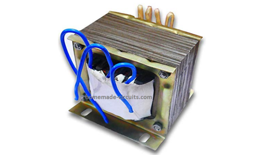
An inverter is your personal power house, which is able to transform any high current DC source into readily usable AC power, quite similar to the power received from your house AC outlets.
Although inverters are extensively available in the market today, but designing your own customized inverter unit can make you overwhelmingly satisfied and moreover it's great fun.
At Bright Hub I have already published many inverter circuit diagram, ranging from simple to sophisticated sine wave and modified sine wave designs.
However folks keep on asking me regarding formulas that can be easily used for designing a inverter transformer.
The popular demand inspired me to publish one such article dealing comprehensively with transformer design calculations. Although the explanation and the content was up to the mark, quite disappointingly many of you just failed to grasp the procedure.
This prompted me to write this article which includes one example thoroughly illustrating how to use and apply the various steps and formulas while designing your own transformer.
Let’s quickly study the following attached example: Suppose you want to design an inverter transformer for a 120 VA inverter using a 12 Volt automobile battery as the input and need 230 Volts as the output. Now, simply dividing 120 by 12 gives 10 Amps, this becomes the required secondary current.
Want to learn how to design basic inverter circuits?
In the following explanation the Primary Side is referred to as the Transformer side which may be connected at the DC Battery side, while the Secondary side signifies the Output AC 220V side.
The data in hand are:
- Secondary Voltage = 230 Volts,
- Primary Current (Output Current) = 10 Amps.
- Primary Voltage (Output Voltage) = 12-0-12 volts, that is equal to 24 volts.
- Output Frequency = 50 Hz
Calculating Inverter Transformer Voltage, Current, Number of Turns
Step#1: First we need to find the core area CA = 1.152 ×√(24 × 10) = 18 sq.cm where 1.152 is a constant.
We select CRGO as the core material.
Step#2: Calculating Turns per Volt TPV = 1 / (4.44 × 10–4 ×18 × 1.3 × 50) = 1.96, except 18 and 50 all are constants.
Step#3: Calculating Secondary Current = 24 × 10 / 230 × 0.9 (assumed efficiency) = 1.15 Amps,
By matching the above current in Table A we get the approximate Secondary copper wire thickness = 21 SWG.
Therefore the Number of Turns for the Secondary winding is calculated as = 1.96 × 230 = 450
Step#4: Next, Secondary Winding Area becomes = 450 / 137 (from Table A) = 3.27 sq.cm.
Now, the required Primary current is 10 Amps, therefore from Table A we match an equivalent thickness of copper wire = 12 SWG.
Step#5: Calculating Primary Number of Turns = 1.04 (1.96 × 24) = 49. The value 1.04 is included to ensure that a few extra turns are added to the total, to compensate for the winding losses.
Step#6: Calculating Primary Winding Area = 49 / 12.8 (From Table A) = 3.8 Sq.cm.
Therefore, the Total Winding Area Comes to = (3.27 + 3.8) × 1.3 (insulation area added 30%) = 9 sq.cm.
Step#7: Calculating Gross Area we get = 18 / 0.9 = 20 sq.cm.
Step#8: Next, the Tongue Width becomes = √20 = 4.47 cm.
Consulting Table B yet again through the above value we finalize the core type to be 6 (E/I) approximately.
Step#9: Finally the Stack is calculated as = 20 / 4.47 = 4.47 cm
Table A
| SWG | AMP | Turns per Sq.cm |
|---|---|---|
| 10 | 16.6 | 8.7 |
| 11 | 13.638 | 10.4 |
| 12 | 10.961 | 12.8 |
| 13 | 8.579 | 16.1 |
| 14 | 6.487 | 21.5 |
| 15 | 5.254 | 26.8 |
| 16 | 4.151 | 35.2 |
| 17 | 3.178 | 45.4 |
| 18 | 2.335 | 60.8 |
| 19 | 1.622 | 87.4 |
| 20 | 1.313 | 106 |
| 21 | 1.0377 | 137 |
| 22 | 0.7945 | 176 |
| 23 | 0.5838 | 42 |
| 24 | 0.4906 | 286 |
| 25 | 0.4054 | 341 |
| 26 | 0.3284 | 415 |
| 27 | 0.2726 | 504 |
| 28 | 0.2219 | 609 |
| 29 | 0.1874 | 711 |
| 30 | 0.1558 | 881 |
| 31 | 0.1364 | 997 |
| 32 | 0.1182 | 1137 |
| 33 | 0.1013 | 1308 |
| 34 | 0.0858 | 1608 |
| 35 | 0.0715 | 1902 |
| 36 | 0.0586 | 2286 |
| 37 | 0.0469 | 2800 |
| 38 | 0.0365 | 3507 |
| 39 | 0.0274 | 4838 |
| 40 | 0.0233 | 5595 |
| 41 | 0.0197 | 6543 |
| 42 | 0.0162 | 7755 |
| 43 | 0.0131 | 9337 |
| 44 | 0.0104 | 11457 |
| 45 | 0.0079 | 14392 |
| 46 | 0.0059 | 20223 |
| 47 | 0.0041 | 27546 |
| 48 | 0.0026 | 39706 |
| 49 | 0.0015 | 62134 |
| 50 | 0.0010 | 81242 |
Table B
| Type | Tongue Width (cm) | Winding Area (cm²) |
|---|---|---|
| 17 (E/I) | 1.270 | 1.213 |
| 12A (E/12I) | 1.588 | 1.897 |
| 74 (E/I) | 1.748 | 2.284 |
| 23 (E/I) | 1.905 | 2.723 |
| 30 (E/I) | 2.000 | 3.000 |
| 21 (E/I) | 1.588 | 3.329 |
| 31 (E/I) | 2.223 | 3.703 |
| 10 (E/I) | 1.588 | 4.439 |
| 15 (E/I) | 2.540 | 4.839 |
| 33 (E/I) | 2.800 | 5.880 |
| 1 (E/I) | 2.461 | 6.555 |
| 14 (E/I) | 2.540 | 6.555 |
| 11 (E/I) | 1.905 | 7.259 |
| 34 (U/T) | 1.588 | 7.259 |
| 3 (E/I) | 3.175 | 7.562 |
| 9 (U/T) | 2.223 | 7.865 |
| 9A (U/T) | 2.223 | 7.865 |
| 11A (E/I) | 1.905 | 9.072 |
| 4A (E/I) | 3.335 | 10.284 |
| 2 (E/I) | 1.905 | 10.891 |
| 16 (E/I) | 3.810 | 10.891 |
| 5 (E/I) | 3.810 | 12.704 |
| 4AX (U/T) | 2.383 | 13.039 |
| 13 (E/I) | 3.175 | 14.117 |
| 75 (U/T) | 2.540 | 15.324 |
| 4 (E/I) | 2.540 | 15.865 |
| 7 (E/I) | 5.080 | 18.969 |
| 6 (E/I) | 3.810 | 19.356 |
| 35A (U/T) | 3.810 | 39.316 |
| 8 (E/I) | 5.080 | 49.803 |


Questions & Answers
Hello Everybody.
Can someone tell why the factor 1.152 is used in calculating the core area? where did it come from. and if possible, is there a formula to be used that states the core area depending on the frequency. I'm asking because i want to use high frequency transformers and i need to know what size for wha tpower
Hello Gober,
The above explanation is solely for iron core transformers not for high frequency ferrite transformers…so the calculations won't work for you.
My answer is
Tpv=1/(4.44*10^-4*18*1.3*50)=1.92?
Thise is right answer?
Please replay question?
yes that's correct
yes, I think the above data is limited for upto 20 amp transformer not above that, so im sorry a 1kva could be too large and not within the range of the above data.
Ashok, please divide 400 by the voltage of the transformer to get the approximate current on the relevant side.
VA = watts – PF
hi friend,how are you and your family.my friend,I want to make a transformer for ups to charge 200 amps battery in 30 minute approximately and give good back up and drive about deep freezer (triplet) an water-pump and five fans,five energy savers at once.please
help me my friend.
hi imam,
you are probably looking at a 10kva inverter design, i have no idea how to design such a huge transformer, please consult a professional trafo designer
Sir,
sir,
i have just salvaged 2 Nos of ups transformers from an old working UPS "Luminous 750va" double battery, i just want to know that can i use them to build an inverter with a range between 200 to 500 watt power inverter for home. second is that i am confused about the connections of these transformers there are 7 wires coming out from one side and three on the other side. how to identify the wires and check their voltages. i have been posting this every where but i idint receive any response. i shall be grateful if you could help me resolve this thing. the transformer has this marking on it " TX-201-1000-02"
Gowhar, While removing you could have at least noted down which taps are terminated as mains outputs for the appliances.
Anyway, you can connect your home AC mains across the different taps of the trafo randomly with a 100 watt bulb in series….the taps which produce minimum glow over the lamp could be assumed as the 220V winding of the trafo….
Once you locate this you can keep the mains input with the 100 watt series bulb connected, and take a DMM for checking the AC voltages across the remaining taps…in this way you can go ahead with the required identifications.
….maintain extreme caution while doing the above as the procedure involves lethal mains current.
thank you very much for the reply
Dear Sir,
i have a question, suppose i will get an inverter and ups with same rating including batteries, will they give same back up time.
waiting curiously for your reply
thanks
Dear Gowhar,
Yes they should have identical backup time
thankyou for the prompt reply.
God bless you.
You don't need to rewind the 1000watt trafo, you can use the same trafo for obtaining lower wattages…the optimization will simply depend on the battery current which can be reduced as per the requirements.
Thanks Ahmad!
By default the 104 caps can be 50V rated, the resistors 1/4 watt rated. I am not sure about the resistor replacement of 200K…can you show me the exact link?
104 means 0.1uF, if your circuit requires 0.1uF, then all these capacitors would be OK.
Your link did not open the circuit page, it opened the homepage of the site….provide the exact link of the diagram, only then i would be able to say anything.
Ahmad, I have checked the link, yes you can use 200K + 100k variable preset a pin#6.
first try with single mosfets only…if it works perfectly then you can add one more mosfet in parallel on each channel.
you are welcome Ahmad
you can use the 6.8v-0-6.8v trafo for the referred circuit application, it will surely work.
220k will be ok in place of 200k.
6.8v trafo will give 400v at the output, you will need to adjust the PWM pot or the load correction pot for adjusting it to 220V.
You can try 12v or other trafos also, if you wish.
Ahmad, don't bother about such details, concentrate on the basic technique and use only the three leads of the mosfet,
use the metal tab for attaching heatsinks only and nothing more.
what is copper plane? do you mean PCB copper ground track?
yes, that's correct
you are welcome!
hi,
can we make an inverter for very small voltages like .5 volts using amplifying transistors like 2n2222 or 2n3904, and the output should be around 3-4 volts ac, that can power 2 leds. if yes can you tell me such a circuit. also about transformer, how does it is built for such a low voltage ?
i need it because i am participating in inspire award.
I think we have discussed this earlier, anyway just to remind you we can use a joule thief circuit for this, you may refer to this article for more details:
https://www.homemade-circuits.com/2012/10/1-watt-led-driver-using-joule-thief.html
is the self looped motor generator is real?
if so why yet, it hasnt come to real world?
it's fake…
you can study Adams motor for getting cold electricity, which is a true concept.
well I am making an inverter which should be of 100 watt using 12v 7Ah battery. Can you tell me a circuit, also I am a beginner in making inverter.
Also my teacher insisted me to put an cooler( i dont no why) off coarse a fan, but i told them that it is not necessary but he made it strict to add an fan. so can you tell me how to add a pc fan to an inverter circuit.
it would be a great help.
thankx
You can try the following circut, it will easily handle 100 wats provided the trafo is correctly rated.
https://www.homemade-circuits.com/2012/09/mini-50-watt-mosfet-inverter-circuit.html
Fix the fan over a suitable slot on the cabinet facing the mosfet heatsink such that it throws the breeze on the mosfet heasink.
I know but where do i connect the power supply for the fan?
obviously it will from the inverter battery
Please do design a 5Kwatt inverter transformer.
this will be much more needed since we are all globally going for green energy. And 5kwatt inverter is much sought after, than low power inverter.
thanks! I'll surely try to present one in this blog sooner or later.
Hai Sir,
For secondary winding should we double the turns that is 49 centre tap 49 total 98 turns or after 24 turns should we take the centre tap and again wind another 24 turns.
Hi Vijeesh,
please explain your question detail, I could not understand what specification you are trying to make.
In the above calculation you got 49 turns for secondary winding.(means in the secondary winding first we will wind 49 turns with 12 swg wire then we take the centre tap then again wind 49 turns,total 98 turns) or we have to take the centre tap from the middle of 49 turns that's after 24.5 turns we take the centre tap and again wind 24.5 turns.
It will be from the center of the 49 turns, that is after 24,5 turns or after 24 turns.
i have an 200watt inverter with two irfz44n mosfets. how can i increase its power to 400watt.? can i add more mosfets in parallel? plz reply soon.
yes it can be tried in that way.
I really appreciate your tremendous effort in help others out. Please sir, I want you to help me calculate the core size for the primary and the secondary, number of turns, the lamination size for 1kva transformer for inverter. I tried using the method you used above but I halted when it comes to choosing thickness of wire for the secondary in the table because I couldn't find there. Please sir. I want you to give me the wire table that starts from 1 and not 10 and also that of lamination table. I had be very grateful if you do that for me sir. Hope to read from you soon sir.
Pls sir. I want you to help me with the calculation for 1kva transformer inverter. I used the above method but the challenges was that I couldn't find the wire thickness from the table you gave above. Please I will be very grateful if u can upload a table that will start from 1 and not 10 for both thickness and lamination. Or if there is another way of doing the calculation let me know sir. Hope to read from you soon.
Thank you khennie, but I am sorry I won't be able to help you with the calculations because I too have no idea regarding the wire SWG calculation which would handle 1000 watts. I got the above data from one of the electronic magazines and I personally do not have any info regarding the specific data that you are asking.
I would advise you to seek the help of a professional transformer maker, he would charge a bit but finally you would be able to achieve the perfect design as per your requirement.
Thanks for your reply,I don't know any professional online but pls if you know one, kindly link me to him
getting it online will be difficult, you will have to find it locally in your area, or in your nearest electronic market
Hi Swagatam,
Can you please help me build a 200amp inverter.