The following concept I have explained a simple yet viable solar grid tie inverter circuit which can be modified appropriately for generating wattage from 100 to 1000 VA and above.
What's a grid tie inverter
It's an inverter system designed to work just like an ordinary inverter using a DC input power with an exception that the output is fed back to the utility grid.
This added power to the grid may be intended for contributing to the ever increasing power demands and also for generating a passive income from the utility company in accordance with their terms (applicable in limited countries only).
For implementing the above process, it's ensured that the output from the inverter is perfectly synchronized with grid power in terms of RMS, waveform, frequency and polarity, for preventing unnatural behavior and issues.
The proposed concept designed by me, is yet another grid tie inverter circuit (not verified) which is even simpler and reasonable than the previous design.
The circuit may be understood with the help of the following points:
How the GTI Circuit Works
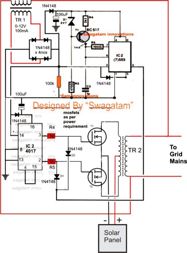
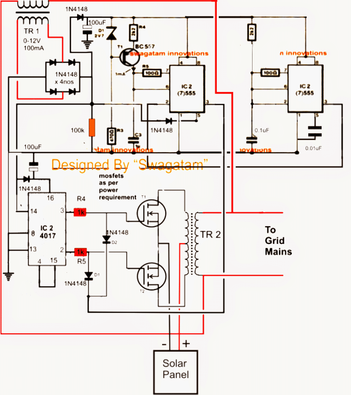
AC mains from the grid system is applied to TR1 which is a stepped down transformer.
TR1 drops the mains input to 12V and rectifies it with the help of the bridge network formed by the four 1N4148 diodes.
The rectified voltage is used for powering the ICs via the individual 1N4148 diodes connected across the relevant pinouts of the ICs, while the associated 100uF capacitors make sure that the voltage is appropriately filtered.
The rectified voltage acquired just after the bridge is also used as the processing inputs for the two ICs.
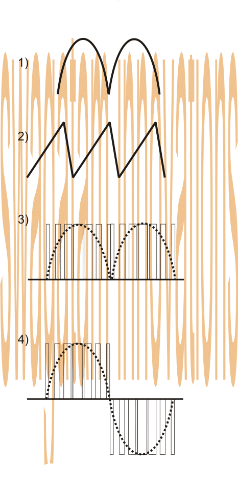
Since the above signal (see the waveform image #1) is unfiltered it consists of a frequency of 100Hz and becomes the sample signal for processing and enabling the required synchronization.
First it's fed to pin#2 of IC555 where it's frequency is used for comparing with the sawtooth waves (see waveform #2) across pin#6/7 obtained from the collector of the transistor BC557.
The above comparison enables the IC to create the intended PWM output in sync with the frequency of the grid mains.
The signal from the bridge is also fed to pin#5 which fixes the RMS value of the output PWM precisely matching with the grid waveform (see waveform #3).
However at this point the output from the 555 is a low in power and needs to be boosted and also processed such that it replicates and generates both the halves of the AC signal.
For executing the above, the 4017 and the mosfet stage is incorporated.
The 100Hz/120Hz from the bridge is also received by the 4017 at its pin#14 which means now it's output would sequence and repeat from pin#3 back to pin#3 such that the mosfets are switched in tandem and exactly at the frequency of 50Hz, meaning each mosfet would conduct 50 times per second, alternately.
The mosfets respond to the above actions from the IC4017 and generate the corresponding push pull effect over the connected transformer which in turn produces the required AC mains voltage at its secondary winding.
This may be implemented by supplying a DC input to the mosftes from a renewable source or a battery.
However the above voltage would be an ordinary square wave, not corresponding to the grid waveform, until and unless we include the network comprising the two 1N4148 diodes connected across the gates of the mosfets and pin#3 of IC555.
The above network chops the square waves at the gates of the mosftes accurately with respect to the PWM pattern or in other words it carves the square waves exactly matching the grid AC waveform, albeit in PWM form (see waveform #4).
The above output now is fed back to the grid conforming the grid specs and patterns accurately.
The power output can be altered right from 100 watts to 1000 watts or even more by appropriately dimensioning the input DC, the mosfets and the transformer ratings.
The discussed solar grid tie inverter circuit remains operative only so long as the grid power is present, the moment utility mains fails, TR1 switches OFF the input signals and the entire circuit comes to a halt, a situation that's strictly imperative for grid-tie inverter circuit systems.
Warning: The author cannot be held responsible for the results of the experiment. Please do it at your own risk!! The projects explained here are recommended only for the experts in the field of electronics.
Circuit Diagram
Assumed Waveform Images
Something's not right in the above design
According to Mr. Selim Yavuz the above design had a few things which looked doubtful and needed correction, let's hear what he had to say:
Hi Swag,
hope you're well.
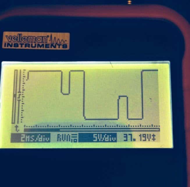
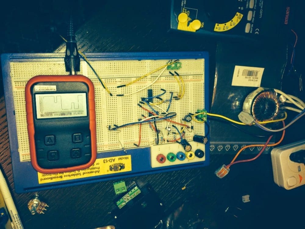
I tried your circuit on a bread board. It seems to work except pwm part. For some reason, I get a double hump but no real pwm. Could you please help me understand how 555 does pwm? I noticed that 2.2k and 1u create a ramp of 10ms. I believe the ramp should be much faster than that as the half wave is 10ms. May be I missed a few things.
Also, 4017 does a clean job switching happily back and forth. When you power up, the 100 hz clock makes the counter always start from 0. How can we assure that it always in phase with the grid?
Appreciate your help and ideas.
Regards,
Selim
Solving the Circuit Issue
Hi Selim,
Thanks for the update.
You are absolutely correct, the triangle waves should be much higher in frequency compared to the modulation input at pin#5.
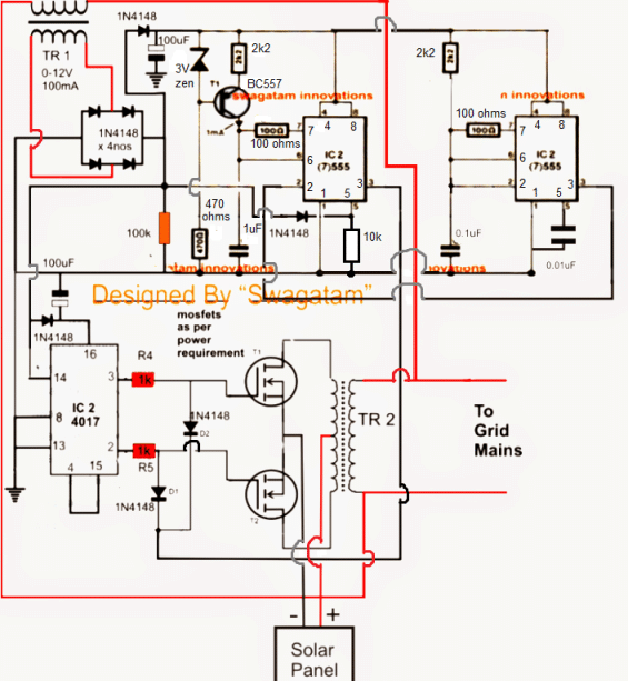
For this we could go for a separate 300Hz (approximately) 555 IC astable for feeding pin2 of the pwm IC 555.
This will solve all the issues according to me.
The 4017 should be clocked via 100Hz received from bridge rectifier and its pin3, pin2 should be used for driving the gates and pin4 connected to pin15. This will ensure perfect synchronization with the mains frequency.
Regards.
Finalized Design as per the above conversation
The above diagram has been redrawn below with distinct part numbers and jumper notations
WARNING: THE IDEA IS BASED SOLELY ON IMAGINATIVE SIMULATION, VIEWER DISCRETION IS STRICTLY ADVISED.
A major issue with the above design faced by many of the constructors was the heating up of one of the mosfets during the GTI operations. A possible cause and remedy as suggested by Mr. Hsen is presented below.
The proposed correction in the mosfet stage as recommended by Mr. Hsen is also enclosed here under, hopefully the said modifications will help control the issue permanently:
Hello mr. Swagatam:
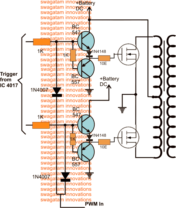
I watched again your diagram and I am firmly convinced that the gates of the MOSFETs will reach a modulating signal (HF PWM) and not a simple signal 50 cs. Therefore I insist, a more powerful driver the CD4017 must be incorporated, and the series resistance should be of a much lower value.
Another thing to consider is that at the junction of the resistor and the gate should not be another added element, and in this case I see going to the diodes 555.
Because this may be the reason why one of the heats MOFETs because it can self oscillate. So I think that the mosfet heats because it is oscillating and not because of the output transformer.
Excuse me, but my concern is that your project succeed because I feel very good and it is not my intention to criticize.
Yours affectionately, hsen
Improved Mosfet Driver
As per the suggestions from Mr Hsen, the following BJT buffer could be employed for ensuring that the mosfets are able to work with better safety and control.
Ideally it is strictly recommended to calculate all the parameters before designing a proper Grid Tie inverter. Below explained are the key formulas and calculations pertaining to grid-tie inverters which includes power, voltage, and efficiency parameters:
Power Flow in Grid-Tie Inverters
Grid-tie inverters are designed to inject power into the grid while maintaining grid synchronization. The key relationship for power flow can be given as:
- Pin = Pout + Ploss
Where:
- Pin = Input power from the DC source (like a solar panel)
- Pout = Output power injected into the grid
- Ploss = Power losses in the inverter (maybe due to switching, conduction, and transformer losses)
Inverter Efficiency
The efficiency of a grid-tie inverter could be defined as:
- Efficiency (%) = (Pout / Pin) × 100
Where:
- Pout = AC power output to the grid
- Pin = DC power input from the source
You can normally assume grid-tie inverters to have have efficiencies between 90%–98%.
Power Factor (PF)
Grid-tie inverters normally needs to operate at a high power factor to ensure efficient power transfer to the grid. The power factor can be calculated as:
- PF = Pout / (Vrms × Irms)
Where:
- Pout = Real power output (W)
- Vrms = RMS grid voltage (V)
- Irms = RMS current injected into the grid (A)
Ideally for any grid-tie inverter you must try to get a PF ≈ 1 (purely resistive load).
Maximum Power Point Tracking (MPPT)
Grid-tie inverters configured with MPPT can adjust the input voltage to maximize power extraction from the source. The key equation for calculating maximum power can be calculated using the formula:
- Pmax = Vmp × Imp
Where:
- Pmax = Maximum power output of the DC source (W)
- Vmp = Voltage at maximum power point (V)
- Imp = Current at maximum power point (A)
Sizing the Inverter
Always make sure the inverter is rated to handle the peak power of the DC source. For a solar panel integration, you can use the following formula:
- Pinv = Parray / ηinverter
Where:
- Pinv = Rated power of the inverter (W)
- Parray = Total power of the solar array (W)
- ηinverter = Efficiency of the inverter (decimal)
Lets solve an Example Grid tie Problem as given below:
Consider we have an solar panel array rated at 5 kW and the inverter efficiency is 95% then the inverter should have a rating of:
Pinv = 5000 / 0.95 ≈ 5263W
RMS Voltage and Current
The RMS values of voltage and current injected into the grid can be calculated as:
- Vrms = Vpeak / √2
- Irms = Ipeak / √2
Where:
- Vpeak = Peak voltage of the AC waveform (V)
- Ipeak = Peak current of the AC waveform (A)
Synchronization with the Grid AC Line
We have to ensure that the inverter must match the grid's voltage, frequency, and phase to inject power. The key relationship is given by the formula:
- Grid Frequency = Inverter Frequency
Total Harmonic Distortion (THD)
The inverter must be designed to minimize the harmonic distortion in the current injected into the grid. This THD can be calculated as:
- THD (%) = (√(I22 + I32 + ... + In2) / I1) × 100
Where:
- I1 = Fundamental frequency current
- I2, I3, ..., In = Harmonic currents
In order to comply with the terms of the grid supply network, make sure the THD is typically less than 5%.
DC Link Capacitor Sizing
In grid-tie inverters we use the DC link capacitor to smooth the input DC voltage. Its value can be estimated as:
- Cdc = Iload / (4 × f × ΔVdc)
Where:
- Cdc = DC link capacitance (F)
- Iload = Load current (A)
- f = AC grid frequency (Hz)
- ΔVdc = Allowed ripple in DC link voltage (V)
Transformer Turns Ratio
If you are using a transformer in your grid-tie inverter for isolation then the turns ratio can be calculated as:
- N = Vgrid / Vdc
Where:
- N = Turns ratio
- Vgrid = RMS grid voltage (e.g., 230V or 120V)
- Vdc = DC input voltage
Reactive Power (Q)
Your inverters can inject reactive power in the grid so if required you can calculate it as:
- Q = Vrms × Irms × sin(θ)
Where:
- θ = Phase angle between voltage and current
Grid Current Calculation
The current injected into the grid can be calculated using Ohms law as:
- Igrid = Pout / Vrms
Example Calculations
Example 1: Efficiency Calculation
- Input power (Pin): 5000W
- Output power (Pout): 4800W
Efficiency = (Pout / Pin) × 100
= (4800 / 5000) × 100 = 96%
Example 2: RMS Current
- Pout = 4800W
- Vrms = 230V
Irms = Pout / Vrms
= 4800 / 230 ≈ 20.87A



Questions & Answers
Hi Roger,
No, it's not a tested design.
hey hi, suggest me tested inverter circuit upto 500-900W
but my input is BATTERY then what should be the specification 12v 7.5A or 12v 50A and specification of transformer
Hi, battery should be at least 200 AH for supporting 500/900 watts
then, suggest me any other circuit which can give o/p around 500W (modified sine wave) using 12v 50Ah battery.
12V/50AH will not be able to sustain 500 watts.
as per load and battery
Mr. Swagatam me interested in this circuit for energy saving but I have some questions. As coupling that this investor has the same voltage that has the mains and what is the voltage at which the transformer should I do that attaches to the network if it is 220 volts AC.
Sorry i did not understand your question.
Mr. Swagatam need some answers on this circuit. I want to know if the power transformer should I do with some specifications or do I just have to output voltage without any variation, I mean, in the normal inverters always the coils are made to a higher voltage and is adjusted with a potentiometer, but no potentiometer here so I want to know what this voltage is synchronized with the network as I do the coil voltage.
Mr.Cabrera, you can use any desired transformer as per the load requirements for this design….no adjustments are required here because everything is auto-adjusted as per the data received from the mains AC into the inverters processing circuits.
Mr. Swagatam excuceme if I cause trouble, but as I am interested in that I want to loop as shown in the schematic, for this reason I want to know: in the part that is marked (1 mA) between the emitter of T1 and R6 which device is this and the other clarification is what is the value of C3 and whether polarized or not.
Mr. Swagatam excuceme if I cause trouble, but as I am interested in that I want to loop as shown in the schematic, for this reason I want to know: in the part that is marked (1 mA) between the emitter of T1 and R6 which device is this and the other clarification is what is the value of C3 and whether polarized or not.
Mr. Cabrera, the 1mA symbol is nothing but an arrow mark, ignore it.
C3 = 1uF or any other lower value will also do, it can be a non-polar type for better functionality.
Mr. Swagatam, this circuit in August had not yet been tested Do you know if maybe this time someone has tried it and if you have made changes?
I am afraid it's not been tested yet completely, Mr. Selim has tried it though but hasn't confirmed the results. I have updated the finalized design…..
Hi Swagatam,
can i use 556 insted of 555?
what is the voltage of the 100uF caps?
how many mosfets if i use IRFZ44n for 1000W?
can u give diagram on how to parallel the Mosfets?
Thanks,
Hi Oiver,
yes 556 can be used here.
100uF voltage rating should be twice that of TR1 output voltage.
you should first try with single mosfets, if it works only then go for more mosfets…
Hi Swagatam,
what about the frequency? is it automatic sync to 50Hz-60Hz?
Thanks,
Hi Oliver,
yes, frequency is also synced with the grid frequency
Hi sir
transformer TR2 (ferrit trans)change to EI trans
Hi Khang,
the shown transformers are iron core type, so you can use ordinary step-up trafos for them
Hi Swagatam Majumdar
transformer ferrit core TR2 change to EI transformer?
thank
yes.
Hi Swagatam…is this the same with the previous circuit…this one look simplier…is this operational? Thanks
Hi Barbe, yes it is simpler since it uses the IC 555 configured to generate sine wave equivalent to grid specifications in a Pulse position modulation mode instead of pulse width modulation.
Both are at par but PPM requires a single 555 IC instead of two as in PWM mode.
It looks a viable design to me.
The previous design was busted is not actually work at all…the mosfet got burn though i follow all what in the diagram its become to hot…i dont even have a chance to check the issue but no output of 220vac….i will try this one if will work…i found some new diagram simple and no need transformer…using triacs..i will check that one aswell
Hi swagatam, appreciate if you could provide me the value of the two mosfet as per 12 0 12 10amps, and c3 value. Thanks for your help
Hi Barbe,
you can use IRF540
Thanks
Hi Swagatam, This is good news..it works…perfect. 🙂
s63.photobucket.com/user/barbe10/media/securedownload_zpsd032c117.jpg.html
I Added the picture of the working inverter. Thanks Again
wow! Good job Barbe.
I'll update the image soon in the above article.
thanks very much.
Hi Swag…I just have little issue..sometimes it just have no output 220vac.
When its no output the Z44N mosfet become to hot.. i dont know really is the issue sometimes it works perfect…but not sure if theout put is actually 60hertz but when I connect a bulb on it..it glows and the voltage from the inverter increase which is good sign its working..i keep you posted what is wrong I will figure it out..
have some issue again when I connec to the grid the inverter the 44n mosfet get to hot…I didn't put a heat sink yet but…I will try the irf540…I 'll keep you posted..what ever I find out. Thanks
I Swagatatam, the normal operation of this inverter should have 220vac output even not connected to the grid or when its not connected to the grid should not have output…l?
Hi Barbe, try putting diodes in series with the drains of the mosfets.
anode to trafo, cathode to drain of the mosfet
use 6 amp diodes.
….also use 12V clamping diodes at the gates of the mosfets.
anode to ground, cathode to gate,
use 1N4007
Sure…i will do that…let you know later…about the success if ever but i think it will work…your the brain of all of this…Im just a crazy hobbyst but not like a designer with a gift like you.
Till next time mate….:) im happy as the inverter is making progress..and its working perfect jus need some touch up…and i think it will work smoothly.
Also if you dont mind appreciated if you could design portable arc welding machine with a small transformer only…Thanks in advance for that…
Thank you Barbe, wish you all the best.
If possible i'll surely try to update the arc welding circuit soon in this blog.
Hi Swag, please check below image if my understanding is correct. Also for both mosfet i need to do it correct. Thanks
s63.photobucket.com/user/barbe10/media/imagejpg1_zps14017bb8.jpg.html?filters[user]=139832643&filters[recent]=1&sort=1&o=0
Yep the polarity and positioning are absolutely correct, but the gate diodes should be 12V zener diodes….not 1N4007
Ok man Thanks….let you know once im done….
Hi Swag…as you've said…I put Diode on mosfet…The response was perfect. I attached the photo…
s63.photobucket.com/user/barbe10/media/IMG_20140408_181706_zps5a8fe189.jpg.html
But, Still little have issue here…both output (live and neutral) of the transformer have voltage..when I used pin type tester. I think neutral must be zero and 220vac live. So I have a doubt to connect to main grid yet.
Also, when I used 10watts bulb it glows perfect and even increase the voltage to 248Vac but when I put my soldering iron 35watts the inverter juz stop working output turn to Zero and after I removed its back to normal…I don't know why…?
appreciated much if you give me info on this one…
Thanks In Advance mate…
Barbe
barbe, you can confirm the "phase" terminal of the inverter output by connecting a load across each of the output terminals and external "earthing"….the terminal which switches ON the load could be taken as the phase.
The neon tester could show confusing results due to the high harmonics that could be present i the AC content of the inverter.
In order to negate this you may try adding a 0.22uF/400V capacitor directly across the output terminals of the inverter trafo, this could possibly correct the neon line tester results.
In the image i can see quite a small battery being used, for a 35watt load you would require at least a 10AH fully charged battery….and the trafo voltage must be a little lower than the battery voltage for enforcing proper results.
…for 12V battery, TR2 must be rated 6-0-6V
Hi Swag… Again its not working..and mosfet 1 connected to 4017 pin#1 getting to hot…??? I dont know why???just a while ago its working perfect….only few issue is the problem…hassh??.-:(
Hi swag…sorry pin# 2 and my 4017 got damged…i juz replace with new one its working again…hope we can make it perfect soon this one mate…..
No problem barbe, take your own time, I appreciate your efforts.
Hi Swag…juz my imagination do you think 2nos. Of 4017ic much better..i dont know???? I just los 3of my 4017..i dont really understand why? Its work perfect…and the next time i check its just not working and 4017 is gone…:(
Hi Barbe, connect the supply to pin16 of iC4017 through a 1k resistor and connect a 12V zener across pin16 and ground, this will prevent the IC from blowing off due to high voltage.
you can do the dame for the 555 supply rails also.
Sure mate…no prob…i will do that after work…!!! Let you know once its done..
Youve said 6 0 6… I use 12 0 12 for 12volts…but later i will connect it to 18vdc 50watts..solar panel and connect it to the grid…what you think do i need to change it now to 6 0 6 or just keep like that…im using this battery just for testing once its perfect and working i will connect to my solar panel…and install to grid. 🙂 thanks Mate
yep 18v for 12-0-12 trafo would be fine, but make sure the voltage to the ICs are given via zener regulation or 78XX ICs..otherwise they will keep frying up:)
Sure…i will do that and keep you posted on the update…!!! How bout my request man…arc welding machine how can i make 18v secondary and 100amps on a small transformer to weld…i have some burn transfo her at my accomodation im planning to make one to use to handle my solar panel….:)…. Thanks in advance man…in advance if u dont min are you a professor in engeneering or are professional scientist something like that u have a lot of knowledge…!!
Thanks mate, yes I am working on that design and will try to produce it soon in my blog.
18V 100amps through a small trafo could be achieved only with an smps topology, i will discuss it in the proposed article.
I am just an hobbyist like you who has been busy in the field since childhood, nothing much:)
youre a kind of humble mate…youre a scientist to me..you share your knowledge to everyone like a teacher…I hope sometimes we can meet and have a cup of coffee..but im in Dubai..and I think you are in india…:)
for the welding machine im excited mate..:)
thanks so much mate, i too wish we could meet someday.
yes, I'm looking for the welding circuit, and will update it soon as per your request
Hi Swag..as you've said..please check the diagram if my understanding on our conversation is correct…:) Thanks Mate
I Attached the link:
s63.photobucket.com/user/barbe10/media/gridtie_zps27cbced1.jpg.html?filters[user]=139832643&filters[recent]=1&sort=1&o=0
Hi Barbe, the junction of pin16 and the 12V zener should be connected to the 1N4148 via a 1k resistor….in your diagram the 1k resistor is missing.
Hi Swag, sorry for the comfusion…you mean after the 4148 diode i will 1k in series to the pin16 of 4017ic and zener diode connected to ground and connected aswell to pin16….sorry again i hope my understanding is correct…!! Correct me if im wrong. Thanks barbe
yes that's exactly what needs to be done.
—–>|—————^^^^———–(pin16)————/<———|iii(ground)
1N4148———–1K————–(pin16)———–(zener)—–(ground)
ah…ok im going to do that after work later…how about the zener diode I put in 555ic is it correct after 4148..i connected the 12v zener diode to it…and ground like this..
in —–>|—–(pin 8 of 555)——{<——|iii (ground) is this correct no need another resistor in series after the 4248 diode?
Thanks..:)
Barbe, the zener connection is correct but it will fry without a 1k resistor from the supply.
so please connect a 1k resistor exactly as we did for the 4017 IC.
I did as I notice on 4017 so I copy….:) Thanks MAte
Hi swag…some issue…when i put the .22uf/275vac…the output voltage drop to 67vac? Any suggestion please
Hi Barbe,yes it will drop a bit but not to this extent, a 50V drop is acceptable not above this,
try reducing the 022 to 0.1uF and check the results.
hi Swag, 0.1uf has no effect the pin bulb became much brighter…:( from 250vac become 245vac and I heard a like FM generator modulated sound from the transformer…if im not mistaken its kilo hertz that sound not sure…so sure but without caps in the output transformer is silent u can heard very tin modulated sound from transformer…:(
Hi Barbe, a slight noise will be heard due to Magnetostriction effect, but the inclusion will help to reduce bad frequencies from entering the grid and produce cleaner sine waves
if you have an oscilloscope you can watch the effects.
You have any suggestion to eliminate the voltage on the output neutral…??? Im out of clue mate 🙂
Hi Swag, i attached the link of the caps i put,
s63.photobucket.com/user/barbe10/media/imagejpg1_zpsc9f563a9.jpg.html?filters[user]=139832643&filters[recent]=1&sort=1&o=0
Thanks….
the cap is OK barbe.
Hi swag…i also put now a 12v zener diode supply goin to both 555 ic…but do i need to put 12v zener diode on ic 1 555 pin#5…and i see some improvement the output ac increase to 250vac and when i put the .22uf the voltage increase to 81vac before it juz 67vac…
Thanks..Barbe
Hi Barbe, pin5 may not require a 12V, however with 12V being used for powering the 555s we cannot use a 18v trafo otherwise the grid-tie handshake will not work….
In this case we will have to go for a 6-0-6V trafo and a 12V batt:D
hi Swag, as per above conversation I take your suggestion using 7812 regulator…could you please check if my understanding is correct…or this will help on the issue because..when everything is fine im going to connect this to grid with the input of 18vdc…Thanks
Here is the link below of the diagram,
s63.photobucket.com/user/barbe10/media/Inverterupdate_zps9fa05ffa.jpg.html?filters[user]=139832643&filters[recent]=1&sort=1&o=0
Hi Barbe, the zener and the 1k connections are spot on….
since the zener is connected the 7812 won't be required and can be removed.
You mean no need for the zener diode since the 7812 is already in….i can take it out on pin 16 ic 4017 and 555 both pin 4,8…am i correct please…?
The only concern to me is pin5 of 555 since later im goin to connect it ti 18dc so if i use 7812 it will protected…???
Please for suggestion
Barbe, it's the opposite that I meant…7812 is not required with zener in place.
as mentioned earlier if we use 12V as the supply for the circuit…18V trafo cannot be used…we'll have to go for a 6-0-6 trafo.
Hi Swag, 7812…is not working…so i turn back to zener diode its working great.
Another issue why thus mosfet no.1 is much hoter compare to mosfet number 2.? 🙁
OK Barbe no problem, zeners look more appropriate.
No idea mate:(, try checking the gate voltages of the mosfets, are they equal?…or may be the gate zeners may be changed to 6V, could help to keep them cooler
ok…mate let me try it..later!!! do you think it is safe know to connect to the grid even I get on my pin type tester a voltage???? on the out put of the transfo?
Thanks Barbe
Hi! swag just an update i made to connect to the grid..seems no problem but i think we have a problem with the frequency…i juz dont know where to adjust or what need to be added…possibly from 555 is the issue…
Regarding the mosfet connected to pin2.. Still to hot…i also add another 6amps diode but still hot…i even reduce the zener to 6v. Im wondering why the voltage sometimes is 260vac..specially when i touch the heatsink of mosfet connected to pin2 of 4017…
Please any suggestion mate im out of clue….:(
Thanks..Barbe
Hi swag, my 12 0 12 burn…and my my mosfet that is always very hot also burn…the primary 12.0.12. But secondary 220vac is ok??…but i dont know why…? Please if you have any suggestion please…please…
Hi Swag, do you think the polarity of the trnsformer may have an effect on this issue…on 12 0 12? Thanks barbe
Hi Barbe, yes polarity is crucial, I have suggested this in the other article.
First confirm whether your inverter is working correctly without connecting it to the grid.
You can do this by connecting a lamp to it.If the lamp lights up brightly would confirm its working.
Next while integrating it to the grid, connect a lower wattage lamp in series with one of the output terminals of the trafo.
and switch on the inverter.
if the lamp lights up would indicate wrong polarity…reverse the wires and repeat the procedure, this time the lamp should be shutof indicating correct phase polarity.
Barbe as mentioned in the article I'm suggesting all these through my assumptions only, and have never confirmed all these practically…so please be cautious about it.
Good luck mate:)
Hi Swag, Thanks for the info… I attached a imaged that maybe a helpful or reason why the mosfet is so hot…could you please if this correct…
s63.photobucket.com/user/barbe10/media/imagejpg1_zps8989a9e2.jpg.html?filters[user]=139832643&filters[recent]=1&sort=1&o=0
Thanks mate….
Barbe, I am afraid that's not correct….the center taps need to be joined together and connected to battery (+) while the upper and lower extreme ends to mosfet drains.
Yes i can confirmed it is working out of the grid…the only issue was the one mosfet is hotter compare to the other one which just normal temperature…? Thanks Mate
im going to try the 6 0 6 aswell..if there is a change..in mosfet temperature…I want it to work mate…appreciated if you could provide everything…:)..:)…I will not stop with this your design…what ever it cos..as I already start on it..so we need to deal with it…
also if you have any latest update on this or anything that maybe I can try..please let me know as I will not retret on this one…really mate…I already blow 3 nos. of transformer 8nos. of mosfet 4nos. 4017ic…how can I stop now..hahahah…
Thanks..Barbe
Quick question mate…on the diagram is the in4148 anode is also connected to pin #2 of IC2 555 and the cathode is on pin#5 yeah? thanks barbe
absolutely mate, that's corect, without it the IC2 pin3 will not produce a synchronized voltage for the grid integration
6 0 6 not working and irf540 is not good to used..i think we need to increase the mosfet rating..i will try irf1010n and let see…!!!!
No, the IRF540 or any mosfet will work, it's not the mosfets that may be creating problems.
Hi Swag, just update sometimes it just not working for no reason..still not working as it should be…anything that maybe u can suggest…!? Thanks barbe
Hi Barbe,
the idea is simple, the voltage from the inverter should be in-sync with the grid…that's the main idea behind any GTI.
you can confirm this by isolating the inverter output from the grid and checking the RMS voltages of the both whether they are synchronized or not.
If the voltages are synchronized, both the counterparts will "shakehands" and serve the purpose as intended.
According to the rule when two identical voltage sources are connected together with correct polarity, the net effect is zero and they won't interact negatively, in this situation the currents of the two counterparts would be simply added.
For example if your GTI generates an accurately synchronized 220V fed back to the grid at say 2 amps, while the mains grid current is say at 32 amps, it may be assumed that you are contributing 2 amps extra to the utility or 2 x 220 = 440 watts.
So the first thing you need to do is confirm whether both the outputs are synchronized or not using an oscilloscope.
as mentioned earlier, the polarity of the phases are crucial.
I hope you got the idea mate;)
Hi Swag…44N Mosfet is better than 540n…and also I spray an insulation varnish on the board and cable to prevent static…seems ok know…I found the neutral aswell..:)…I also remove the 12v zener diode on 555 and 4017…input is normal even I put 18vdc…10volts on 555 12 to 13 on 4017…let me know if should I put back the zeners… thanks barbe
Hi Barbe,
at 18v the ICs could get damaged, not sure how you are getting the results?? better make it into 12v before feeding them to the ICs.
ah ok…let you know then later I will put it back,…the zener diode…regarding the phase I think it is in correct phase..the buld did not light up..i even touch the neutral..its zero…will for being crazy sometimes.. I got electric shock on the other cable…hahah..:D
thanks mate for the info..
you seem to be a mad crazy scientist (just like me) haha…just joking mate.
Will..im just a follower mate…and a big fan of yours…!!!
Hi Swag as an update i attached a link below,
s63.photobucket.com/user/barbe10/media/imagejpg1_zps2eb32e0e.jpg.html?filters[user]=139832643&filters[recent]=1&sort=1&o=0
I change the zener diode on going to the mosfet 12v…but i did not put the zeners to all the ic…seems all the voltage stable…both mosfet are in normal temperature…diode from transfomer is normal….main transformer not hot…everything is normal…im juz waiting for the portable osciluscope that i buy from china… Jejej..hopefully by tomorrow i can get it…
Voltage on 2 555ic – 5-9vdc
Voltage on 4017 – 11-12vdc
Thanks Mate….
That's great mate, hopefully the scope will solve all issues that we are facing right now,
best wishes to you.
Hi Swag,… Any idea why im getting this reading i attached the link below,
s63.photobucket.com/user/barbe10/media/imagejpg1_zps6e6ab845.jpg.html