If you are looking for a power transistor able to support high current upto 25 amps and yet not incorporate the traditional cumbersome TO-3 package, then the TIP36 would certainly impress you.
High Current from Smaller Package
The package of TIP36 is TO-3P which means the accompanied heatsink would require just a single hole to be drilled and the device could be easily soldered over a PCB along with the heatsink, quite unlike the devices which are in TO-3 packages.
You would be surprised to know that this device is a lot advanced and powerful than the more popular MJ2955 (complementary pair of 2N3055) in terms of voltage and current ratings. Comparatively a TIP36 exhibits excellent high gain performance even at low or compressed saturation base voltages.
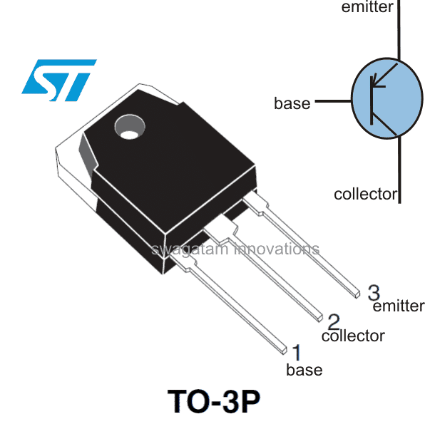
Let's proceed and learn the datasheet and the specifications of this outstanding high current transistor - the TIP36:
Typical Applications:
- Audio Amplifier
- Inverters
- Motor Control
- Solar Chargers.
Absolute Maximum Ratings:
The device will not tolerate anything above the following parameter magnitudes:
- Collector-base Voltage (Vcbo) = 100 volts
- Collector Emitter Voltage (Vceo) = 100 volts
- Emitter Base Voltage (Vebo) = 5 volts
- Collector Current (Ic) = 25 Amp continuous, peak 50 Amp for 5 ms only.
- Base Current (Ib) = 5 Amps
- Max Operating Junction Temperature = 150 degrees Celsius
Complementary Pair
TIP36 can be paired with TIP35, they both are ideally suited as complementary pairs.
Application Note:
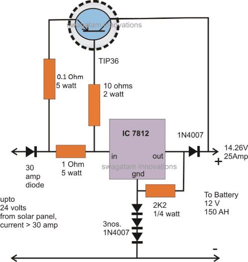
One interesting and very useful application circuit using a couple of TIP36 transistor can be made for charging high current batteries in the order of 150 AH, directly from solar panels.
Derate linearly to 150°C free air temperature at the rate of 28 mW/°
The circuit shown above may be used for charging 12 V batteries having in excess of 100 AH capacities.
To enhance the current gain of the circuit, you can add a TIP127 with the TIP36, as shown below. Remember both the transistors will require a large heatsink, possibly with a fan cooling.
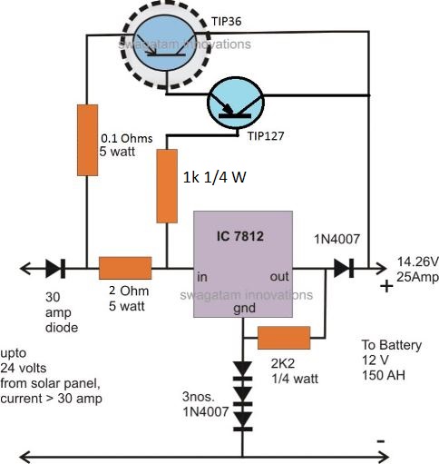
The circuit may be understood as follows:
How TIP36 Works to Produce High Current
The voltage from the solar panel enters the IC7812 first, the three diodes connected at the GND of the IC elevates the output voltage to about 14.26V which is the ideal voltage for charging 12V batteries.
However at this point the TIP36 stays inactive, because of the absence of any voltage across its base/emitter 1 Ohm resistor.
Once the output of the IC 7812 is loaded, sufficient voltage develops across the 1 Ohm resistor for saturating the TIP36 transistor.
The transistor conducts and shifts the required amount of current at the output.
However, in the course the transistor also tries to transfer the entire solar panel voltage to the output. As this tends to happen and the instant voltage at the output tends to go beyond the 14.26 mark, the IC7812 becomes reverse biased and stops conducting.
With 7812 not conducting, voltage across 1 Ohm resistor becomes zero and the transistor inhibits the flow of the voltage.
Due to the above action, the voltage tends to fall back below the 14.26 mark, which instantly prompts te IC to conduct and the cycle switches rapidly producing a voltage that's exactly 14.26 at the output.
Thus the IC is only responsible for holding the voltage to the set limit while the transistor TIP36 becomes responsible for delivering the required high currents.
Note: Use a common heatsink for the IC7812 and the transistor, this will ensure complete safety to the transistor from thermal runaway situation. Be sure to use mica isolation kit for fixing the devices over the common heatsink.


Questions & Answers
Which car amp has the most tip36c transistors in it?
Like 24 32 + in one amp, is there any?
Can this Transistor be configured with Lm317 to vary the voltage for a precise high current supply?
yes that’s definitely possible…
Hi,
I have a “JBL Sub200” audio amplifier that is operated based on a TIP35CW/TIP36CW circuit.
I changed many components on the circuit board including the TIP35CW/TIP36CW. However both TIP35CW/TIP36CW are the first to burn and become shorted upon turning ON the amplifier, even without getting hot.
What could be the cause for them to be the first to burn immediately knowing that they are 100V 25Amps, i.e. highest rated among all the other compnents.
They are powered by a AC transformer outputing 60V AC and 36V AC then rectifier bridge plus capacitors for the DC?
I already cooked 3 pairs of these TIP35CW/TIP36CW
Any hints?
Hi, did you adjust the quiescent current of the amplifier. If you don’t set the quiescent current, the transistor will unnecessarily draw huge current and get destroyed. Connect 100 mA bulbs in series with the +/- supply lines of the amplifier, then adjust the quiescent current preset so that the bulbs just shut off.
Before doing this make sure to keep the input terminal shorted to ground.
Hi there,
I have a question regarding the TIP35-36 complementary pair:
I work on older GK 250ML amps quite often. These amps use the TIP33C-34C pair on the outputs. I have always been curious if I could sub the TIP35C-36C in place of the 33C-34C. These do have a thermal feedback loop A06 to prevent runaway. Did not know if the higher current capacity would alter the feedback and bias.
Just looking for an opinion, I have never tried it, but the 35-36 pairs are everywhere in the 247 case.
I would paste schematic, not sure if I can.
Best Regards,
thp
Hello, it is definitely possible to replace TIP33C/34C with TIP35C/36C as long as the supply voltage is below 100 V.
Sorry I am not sure about the feedback working of your amplifier, so I can’t suggest much about it.
Hi my name is john and I liked the project solar battery charger using the tip 36 transistor I liked the way the diagram showed the orientation of the components it showed the acual pinout of the reg as is I have been studying electronics for 20 years and I think diagrams should show the pinouts for example every time I see a transistor in a diagram I have to refer to my manual for the correct pinout when it can be shown on the acual diagram at glance the orientation of each and every part. kind regards john
I am working on building this circuit but I am confused on the NPN and PNP power transistors .It calls for 0500 NPN
power transistors cant find that transistor. It also calls for tip 36 PNP power transistors. this is a strobe light i want to build any help would be much appreciated.
Thank You,
Scott Hetland
what is an 0500 NPN power transistor
I am not sure which circuit and which part number you are referring to?
TIP127 and TIP36 are both PNP BJTs. If you cannot find them, you can try TIP2955 and 2N2907
John papa, the actual pinout of 7812 is exactly same as shown in the square symbol. Holding the printed side towards you, left pin is input, center pin is ground, right side pin is out.
I used 2N6653 in a similar diagram and it became hot shortly at a current of 3 amps with cooler but no fan,and this one is rated at 20A and150w
apply heatsink compound and a large finned heatsink and then check…the issue here is whether it can withstand the rated amount of current or not, and the datasheet can never be wrong, unless the device is duplicate or substandard
the data sheet is correct, the understanding is missing.I make everything right, I’m not a beginner.The transistor is original,what I want to tell you is that the reality in electronics is quite different, than in theory
Then probably you should tell this to the datasheet creator or the engineers who have written the datasheet without any special remarks.
TIP36 can only support 25 amps if the temperature of the PN junctions does not exceed 25 degrees Celsius, which is practically not possible.
That’s not correct. TIP36 is rated to dissipate 125 watts without heatsink if the ambient temperature is at 25 degrees Celsius. It is definitely rated to work with 25 amps if adequate heatsinking is provided.
This is my interpretation about the Pd, because I can’t figure out what the 125 watt indicates? I can’t find a clear definition for this anywhere on the internet
in completely open state (saturation) the transistor has Vce0= 4 volts at a current of 25 amps so a power dissipated 100 watts. The remaining 25 watts are dissipated by the emitter base junction, total 125watts.this at 25 degrees celsius.as the temperature of the junctions increases, the dissipated power decreases by 1wat per degree celsius.so at 50 degrees celsius it can dissipate only 100 watts and at 100 degrees celsius only 50 watts,and this only in the saturation state.in our diagram the transistor does not work in saturation mode so the dissipated power increases significantly up to 160 watts so for this reason we need more transistors in parallel,each with its 0.1 ohm emitter resistor.
125w in our case, represents the maximum power that can be dissipated by the PN junctions and is UxI, meaning the voltage difference between the collector and emitter multiplied by the current that flows.so,if we supply the diagram at 24 volts and at the output we have 14 volts the difference of 10 volts we find it on the transistor (resistor + diode).at 25 amps current at 0.1 ohm resistor will be 2.5 volts, at diode pins 1 volts total 3.5 volts.the transistor will have 6.5volt terminals which multiplied by 25 amps results 165wat which the transistor does not support. so I say that the diagram is not good. I hope you understood.
please check active region safe operating area and power derating rate depending on the capsule temperature rise for TIP36 and you will see why it is actually used at 50-60w dissipated powers and 6-8amps load
I know that, so please maintain 25 degree Celsius to prevent derating, if you can’t then its your problem not the transistors problem. I have only shown the maximum feasible limit in the diagram as per the datasheet.
this schematic diagram is wrong
You only have to tweak the resistor values to get the right amount of current. The schematic is CORRECT!
if we mount 3 transistors in parallel then maybe we have 25 amps at the output
practically TIP36 is used at dissipated powers around 50w.so two TIP36 is not enough.
Try it yourself, just make sure to add sufficient heatsink
ok, it is correct as a working principle, but with current values it can only deliver 1 or 2 amps, not 25 amps as you say. even if you reduce the R value to 0.1 ohms it still cannot deliver 25 amp.TIP36 could not dissipate as much power.
The TIP36 is rated at 25 amps, so it is designed to deliver 25 amps if sufficient heatsinking is provided.
I know that, but these are the absolute maximum values.It cannot be practically reached. Even if the diagram is powered by 24v the transistor must dissipate approximately 200w
what i mean is that,in the current configuration the diagram cannot deliver more than 5 or 6 amps with R0.1ohm without being destroyed by overheating
As i said you have to apply a very good heatsink, after all the metal area of the transistor is so small, how can it dissipate so much heat so quickly.
The heatsink can be very large, that’s a different issue. Datasheet has clearly suggested that the device is designed to work with 25 amp continuous current, and I am sure they must have also applied some margin to it.
Yes I agree, so here too it is assumed to be the absolute maximum value. If datasheet suggests that the device won’t burn until 25 amp is exceeded, the above article also refers to the same data. Moreover it is possible to include a 24 amp current limit by adjusting the various resistors
Well done sir, what is the efficiency of this circuit. Thanks teacher
Efficiency will be high when the input output difference is low, and vice versa.
thanks for your quick reply sir am very grateful
you are welcome!
sir does that means i will add more diod at the ground of the 7824 to obtain the 24v
7824 will give you 24V directly, you may have to attach 7 diodes with a 7824 ground lead to get around 29V at the output
29V is required for charging a 24V battery
sir i want to use the circuit with a24v batteries what are the changes i need to make thanks for always been there for me
You may have to replace the IC with a 7824 and configure it in a similar manner
Sir ,how much the ampire of IN 4007 diode?
1 amp max limit
Are you sure tha emitter resistor, on schematic, is 1ohm/5w?
I was referring to the vertical one, the horizontal one is reasonably correct.
It's arbitrarily chosen, you will have to experiment the value with some trial and error, until the correct amount of current is measured at the output
Hello! When I try this circuit with a power source at 20V I got 14.4V in output at 0.4 Amps when I plug in a 12V 7Ah battery. The 7812 gets hot but tip36 doesn't seem to be working. When i measure voltage in 1 ohm emitter resistance and in 2 ohm base resistance they are almost 0. Is it normal? Should I try to plug in the 150W solar panel and a 100Ah battery? Thanks!!!
Hello, the TIP36 will conduct only when the voltage across its base emitter resistor is around 1V.
If you are getting 0.4amps at the output then the voltage across the TIP136 base emitter could be
V = IR = 0.4 x 1 = 0.4V,
so in that case the BJT will hardly conduct….you can try increasing the 1 ohm to 2 ohms or use a higher rated load that would consume at least 1 amp from the IC.
Thank you Roger, I am glad you liked my site,
God bless you too!!
Its my first time here. I really appreciate for your job well done.
Thanks for the everything it is very much interesting topics.
Im Roger from the Philippines. May God bless you always.
Best regards,
Hello i want to charge lithium ion battery with high current with minimum input voltage of 5v and charging current should be 0.7A please suggest circuit with high charging current capability.
you can try the last circuit from this article
https://www.homemade-circuits.com/2013/12/usb-automatic-li-ion-battery-charger.html
Hi, im a newbie at electronics. The L7812CV is an IC7812? Thanks!
L7812 is IC 7812, so it's OK
Excuse me, i'm new at electronics. This IC 7812 is an L7812CV transistor? Thanks!
sir the current from the regulator increases if i increase the resistance value given from dc source to the regulator pin#1.. i have used one 100 ohm 1 W resistance instead of the 1 ohm 5W one and it results in an output current of 70 to 75 percentage of the maximum current that can be delivered directly from the source..
RT, increasing the resistor value will decrease the current and vice versa from the transistor….please make sure you are doing the procedures correctly.
sorry sir i cant do that coz i need a stable 15 V supply which can be used for other purposes also.. and one more the circuiy given in this blog with TIP36C is not working.. the output current isnt increasing…
I have explained the working principle of the circuit in the article, you can refer to it and troubleshoot the fault in your design, or try a different transistor instead of TIP36
sir could you please tell me how to take high current from a -ve regulator ic in a way similiar to the one explained here. mine is a +18v 0V -18V dual supply capable of delivering maximum of 6A current.. i want operate 2 TDA2030 Ics in bridge mode as a 40W subwoofer amplifier. since the maximum supply voltage that this ic can handle is -18V and +18V as Vss and Vdd i need to reduce the voltage down to 15V . so i have used 7815 and 7915 for that.. now comes the problem of current delivery.. so please suggest the way by which i can efficiently connect one or two TIP36s to draw sufficient current for the load
RT, an easier option would be to eliminate the LM7815/7915 and use series diodes for dropping the excess 3 volts
so it is not necessary to use mica isolator to mount ics to heatsinks independently .. right ?
yes, there's no need, in fact adding mica makes heat transfer much inefficient.
sir why we need mica isolation kit for fixing a voltage regulator ic to heat sinc ?
RT, when two devices are mounted over a common heatsink and their bodies are not supposed to come in contact with each other then mounting them through a mica isolator becomes mandatory…which prevents the device body from touching the heatsink and from shorting circuiting
Hi, Thanks for the great circuit
im just curious and want to ask about the power rating
if this circuit outputs 14v @ 25A
thats about 350W of power, but TIP36C is only rated for 125W
how can it handle all of that power ?
Hi, according t me, the 125 watt is the power limit at which the device will generate sufficient heat to destroy itself…in short 125 watt is the max capacity of the device without a heatsink.
with an optimal heatsink (cooling) this device would be able to provide you with the full 350 watts.
I only want 14v 6amp output that's why i use tip42 and i don't think there is something wrong with that since it's only there to produce 6amp current…what will happen if i remove the resistors at the base and enmiter of the transistor…i will try using 18v transformer as input
OK, that will do, I confused your comment with the comment previous to it. you can try removing the emitter.base resistors (vertical ones), these were included for extra safety to the transistor, anyway you can try removing them and see the response….
Goodevening sir,i have implemented the above circuit and i'm using a 12v 3ah transformer 6a10diode inplace of the 30amp one and tip42c inplace of tip 36 and 4 1n4007 diode at the adj of 7812 but i'm only getting 12.5volt and sometimes it increases to 13.8volt and back to 11.90-12.8v with current of 0.4amp could this be that the transformers voltage is too poor to provide steady 14v after rectifying? also(2)when i disconnect the collector of the tip42c from the positive line the output voltage becomes 0.7-1.2v and when i connect it back it increases to 11.9-13v is that ok?
without load the output from the 7812 must show 14V, if the input is also around 14 to 15V…all your results look incorrect there could be something wrong in your circuit.
TIP42 won't be required for your application….it's only for charging high AH batteries in the range of 100AH
excuse me sir ,
If i want to use TIP36 and LM317 that i want current and voltage of charger about 5AH,12V.
I have my schematic and i can send to your check ?
you won't need a TIP36 stage for a 5ah battery, you can use the LM317 regulator output directly for charging the battery
What if i use a 10amp transistor will it output 5a
yes it will…
Hi sir, can i use 18v 5amp transformer at the input with a 6amp diode to replace the 30amp diode to get 14v 5amp output or are there anymore changes i want to add a 741 automatic stage to the above design
Hi Victory, you can use this circuit for the said application, however for 5amps, TIP36 won't be required, you could use a TIP32
hi swagatam
this is srinivas
thanks for sharing
ihave made this circuit its working fine for some time After that 7812 regulator is became hot & blew
please sugest me
thanks & regards
Hi srinivas,
the 7812 can tolerate upto 30V easily, so 18v is fine and it can be from any DC source, no issues.
hi swagatam
yes iam check it out input voltage is 18 volts
here the main thing is iam not getting 18 volts from solar it is 18-0 volts transformer
is it ok to check the circuit, and another thing is iam replace another 12 volts regulator after that it is working fine
thanks & regards
hi srinivas,
the 7812 IC will never blow as long as the input stays within 30V or the pinouts are correctly assigned.
so please check the input voltage whether it's within 30V or not.
Hi what if lwant to charge 400AH
You can replace the power transistor with an FET rated at the specified level.
Dear sir , what type of a diode is used before the 1 ohm 5 w resistor in the circuit. I don't know about such a diode which is rated 30 amp. Will you please help me sir?
DearArun,
It's a rectifier diode, its current rating should be more than the maximum charging current or the load current at the output
Hi..It's great to see this sort of resource freely available and supported..I've been searching unsuccessfully to find a 10 amp (or similar)constant current battery charger circuit for 12v lead acid batteries using an LM317 with power transistors inside the feedback loop. I have seen the many simple circuits for <1.5 amps but no application notes seem to cover that. Do you have one or can you link to one ? I realise that voltage sensing will have to added to prevent overcharging but I can cope with that. Thanks.
The above circuit can be utilized for the intended purpose but it will require an additional current limiting stage for the current limiting.
I'll try to update the design hopefully soon.
Alternatively there's one much easier option as shown in the following diagram, you can directly operate the circuit in conjunction with any suitably rated DC power supply for charging the battery. The output will be current controlled and safe.
https://www.homemade-circuits.com/2011/12/make-hundred-watt-led-floodlight.html