A DC to DC converter is basically a switch-mode power supply, designed to work either as a boost-converter to step-up a low voltage DC to a higher voltage DC, or as a buck-converter to step-down a higher voltage DC to a lower voltage DC.
The switched mode conversion ensures that the power transfer in the process involves minimum losses, and the efficiency rate is high, typically over 90%.
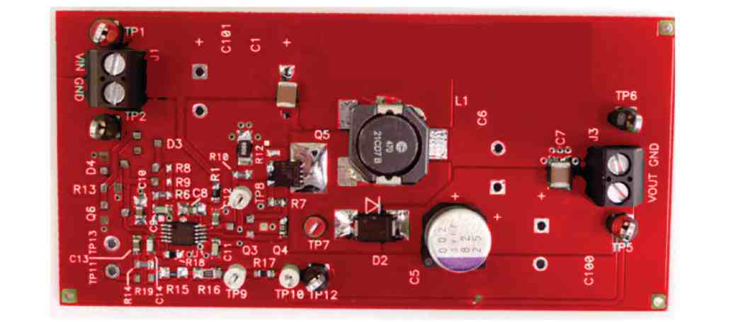
The high efficiency rate in terms of power transfer is the main advantage of using SMPS (switch mode power supply) converters, as opposed to linear regulators which can dissipate and waste huge amounts of power during the DC to DC conversion process.
The main component in an SMPS that enables the efficient power conversion is the inductor or a ferrite transformer based coil, controlled or switched by PWM.
The pulse width modulation or the PWM plays an important role for switching the inductor through a power transistor with calculated duty cycle so that the inductor is able to implement the DC to DC conversion with maximum efficiency.
Since the PWM becomes the crucial factor in an SMPS, an ideal PWM generator/controller IC such as SG3524 or LM3524 becomes extremely suitable for making these types of buck and boost converter designs.
In this post I will elaborately explain regarding how to design and construct DC to DC converters using the IC SG3525.
In one of our earlier posts I will comprehensively explained the main features and the working of this versatile PWM IC SG3524. In the following paragraphs we will see how those features could be practically exploited through simple smps converter designs.
Low Current Boost Converter Circuit using LM3524 IC
The first design below shows a straightforward low power boost converter circuit which uses the internal BJTs of the IC SG3524 for the switching, and therefore the maximum current is limited to 80 mA.
This circuit can be used for converting any low voltage (above 5 V) to a desired higher level, across VO and GND.
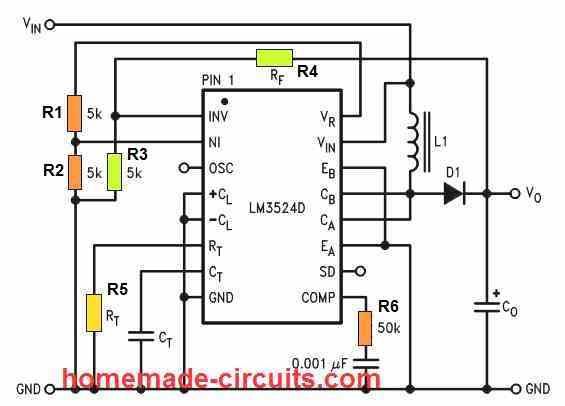
In the above simple SG3524 boost converter design we can see the collectors of the internal driver BJTs CA and CB are joined together for enforcing the ON/OFF switching of the inductor L1 through an appropriately calculated PWM rate.
The PWM rate is set by configuring the SG3524 error amp inputs INV and NI, which is internally set as a comparator, and whose output controls the output PWM.
Setting up the Error Amp for PWM Control
Configuring the error amp is basically implemented by calculating the potential dividers at the INV input through the feedback RF resistor and associated 5 k divider resistor (R3 and R4 shown in green).
This feedback potential at the INV input determines the output pulse cut-off threshold, and the PWM duty cycle.
This threshold limit is fixed with reference to the sample voltage set at the NI input of the error amp through the two 5 k resistors (R1, R2 shown in orange).
Calculating the Feedback Resistor
RF = 5k [(VO / 2.5) -1] = 5000 [(VO / 2.5) -1] this equation sets up the feedback resistor for the PWM control, using the parameters VO = output step-up voltage, and R3 = 5 k.
Calculating Oscillator Frequency
fOSC = 1 / RT * CT this equation sets up the frequency of the converter, which must be anywhere around 30 to 100 kHz. Higher frequencies will mean small L1 inductor.
Calculating the Inductor
L1 = 2.5VIN2 (VO - VIN) / fOSC * IO* VO2 this equation help us to determine the inductance rating for the L1 inductor, using the parameters VIN = input supply voltage, the VO = output voltage, f OSC = frequency, and the IO = output current
Calculating the Output Capacitor
CO = IO(VO - VIN) / fOSC * ΔVO * VO this equation helps us to calculate the output filter capacitor CO, using the parameters IO = output current, VO = output boosted voltage, VIN = input supply voltage, fOSC = frequency, ΔVO = peak-to-peak output ripple.
High Current Step Up Converter
In the above DC to DC step-up converter circuit, I have explained how the SG3524 could be configured as a low current step up current without involving external power transistors.
The next diagram below shows how the same concept could be upgraded to a high current DC to DC boost converter circuit using the very same SG3524 circuit, except the output stage where high power transistors are used for facilitating the required current amplification.
This circuit can be used for stepping up or boosting any low voltage (above 5 V) to a desired higher level, without any limitations in the current level.
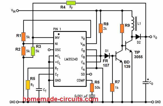
The calculations will be the same as the previous concept.
R9 will depend on the output current spec of the converter, and could be calculated using the formula:
R9 = (VIN - 0.7) * hFE / Max IO
Here, VIN is the input supply voltage, hFE is the current gain of TIP3055, and IO is the maximum output current.
Step-Down Buck Converter using SG3524
The next DC to DC converter circuit using SG3524 discussed below is a step down buck converter which will allow you to convert any higher level DC voltage (below 40 V) into a desired lower DC output voltage, but with an input current not exceeding 80 mA.
Meaning, suppose you are trying to make a 48 V inverter, in which the oscillator circuit can work only with a regulated 15 V DC. In such a situation you can effectively apply this buck converter concept for stepping down 48 V to 15 V DC for powering the oscillator circuit safely and allowing the 48 V to be used by the inverter power devices and the transformer.
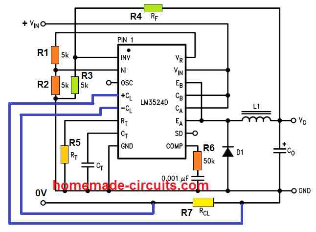
In this configuration we find the IC SG3524 pinout features are configured in the following manner:
The emitters EA and EB of the ICs output transistors are joined together for driving the inductor L1, while the collectors CA and CB are joined together with the input supply Vin for supplying the current to the L1 via the emitters.
The feedback resistor RF (R4) along with the associated 5 k divider resistor R3 is configured as before with the error amplifier, while the reference to the error amp is rigged using R1, R2 via the +5 V supply from the VR (VREF) pin of the IC. This takes care of the PWM control.
High Current Step-Down Converter
In the above example I have explained the low current version of the SG3524 DC step-down converter, without involving external power devices.
For higher current levels, an external power switching transistors could be added, along with other upgraded components such as the L1 inductor and diode.
Meaning, this design can be used for converting any voltage below 40 V to a desired lower level, without any restrictions on the output current level.
An example design for this can be witnessed in the following diagram:
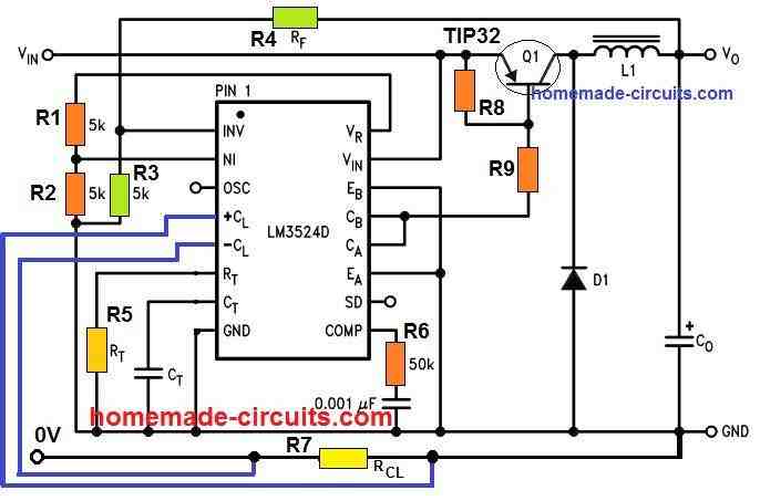
Calculations
The various equations and calculations involved in this SG3524 buck converter circuit can be learned as given below:
Calculating the Feedback Resistor
RF = 5 k [(VO/2.5) - 1] 5000 [(VO/2.5) - 1], this equation is used for fixing the feedback resistor RF(R4) which controls the output PWM
Calculating the Current Sensing Resistor
RCL = Current Limit Voltage / IO(MAX), this equation is used for evaluating the current sensing resistor RCL or the R7, with respect to the maximum desired output current limit IO(MAX) .
The current limit voltage refers to the desired voltage drop that needs to be developed across RCL when IO(MAX) is reached. This current limit voltage could be anywhere between 0.3 V to 1 V, the smaller the better to ensure a smaller RCL
Calculating the Oscillator Frequency
fOSC = 1 / RT*CT this equation allows us to set up the oscillator frequency of the converter, and this can be anywhere between 30 kHz and 100 kHz. Higher frequencies will cause the L1 to be smaller and vice versa.
Calculating the Inductor
L1 = 2.5VO (VIN - VO) / IO*VIN*fOSC this equation can be used for determining the inductor L1 value which becomes the crucial element of the step down converter. In this equation, VO is the desired stepped down output voltage, VIN is the input supply voltage, IO is the maximum output current, fOSC is the oscillator frequency.
The 2.5 value is acquired from the reference voltage formed by the resistive divider using the two 5 k resistors R1, R2 at the NI input of the SG3524 IC error amp.
Calculating the Output Capacitor
CO = (VIN - VO) VO* T2 / 8 *ΔVO *VIN*L1, this equation facilitates determining the output filter capacitor CO, using the available data such as the input supply VIN, output stepped down voltage VO, output peak to peak ripple voltage ΔVO, the inductance of L1, and the period T2 where T = 1 / fOSC
Current Control
In this buck converter we additionally see that current sensing pinouts +CL and -CL of the SG3524 are configured for implementing output current limiting, or for delivering a constant current output for the converter.
The +CL and -CL current limit op amp provides a quick facility to configure the current limiting feature, which overrides all other control feature in the SG3524 IC. Meaning, if the current control feature detects an over current situation, it will override all other features and try to shut down the output of the IC.
Why Over-current shut down is Important in Buck Converter
We already know that the efficiency of this SG3524 buck converter will be very high, may be around 95%. This implies that if the output voltage is stepped down, will result in the output current to rise proportionately.
As an example, suppose we have VIN = 35 V, and we want the output to be VO = 5 V.
If we assume the input current to be 80 mA for the above design, will mean an input wattage = 2.8 watts. This also means that ideally the output current should be then 2.8 / 5 = 560 mA.
Considering the 95 % efficiency, this current still will be in the vicinity of 532 mA, which is a whopping 7 times higher than the input current.
Due to this current boost, a current limiting or current control feature becomes crucial in these step down DC to DC converter designs.
Application
The main application of an SG3524 or LM3524 DC to DC converters can be found in the field of solar controllers.
Solar panels are mostly available with high voltage, low current specs, while batteries are mostly manufactured with lower voltage, higher current (Ah) specifications.
A step-down buck converter becomes highly suitable for integrating a high voltage, low current solar panels with a high Ah, low voltage battery, and ensures a highly efficient and convenient way of implementing solar battery charging.
Courtesy: Texas Instruments
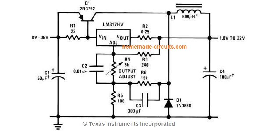


Questions & Answers
Please I need 12v DC to 35v DC boost converter circuit with components or parts list
Please try the following article to design your own boost convetrer:
https://www.homemade-circuits.com/ic-555-boost-converter-calculator/
Please can you help with a complete circuit that can be used to step down 220v AC to 24v DC using this sg3524 buck converter in this article.
Sure, here is the basic design which you can optimize further depending on the load specifications:
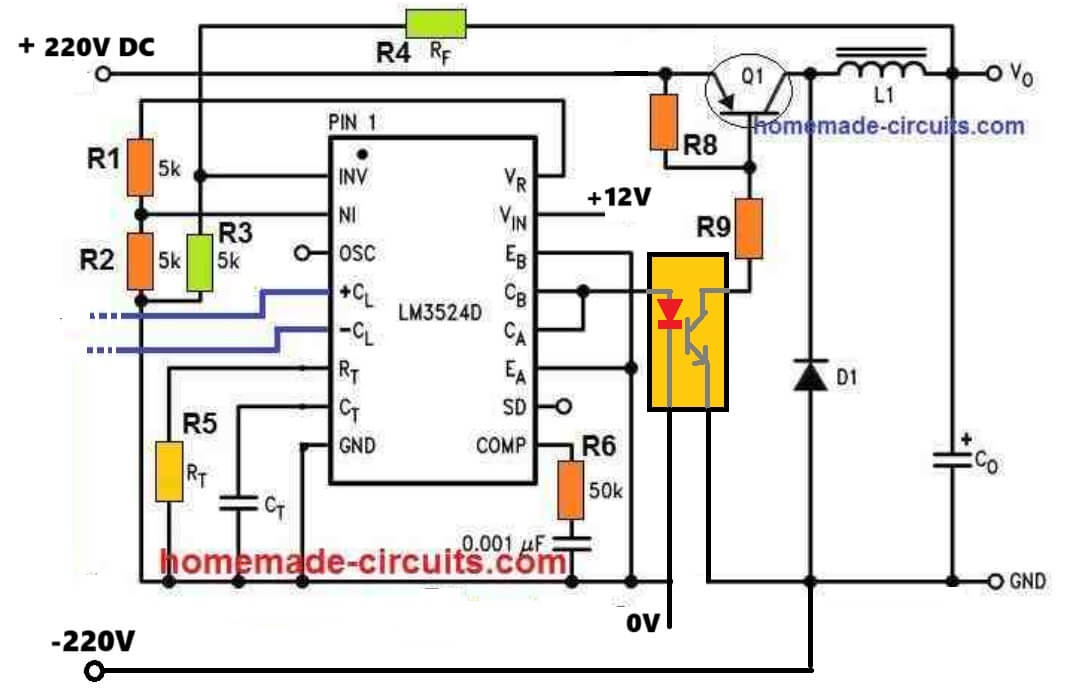
Thanks sir, this kindly help with values for r8 and r9
No problem Bay, R8 can be 10k, R9 will depend on your load current specifications.
You can use the following software to calculate it:
https://www.homemade-circuits.com/transistor-bjt-base-resistor-calculator-software/
Hay its me again, looking at your buck boost converter, I have a similar one using the sg3524. Here is my problem, the mosfets I was using where hy3408 to-220. So fat a have blown up about well close to 100, I thought that I would try a better mosfet like irf260n, which I am doing now, don’t know the out come. I have read that the IGBT is a great transistor. Now I know that they need a higher gate voltage and a lower frequency around 10k. So I got all done, turned it on and no smoke came out, the voltage output was correct, so I put a 120 watt load and worked perfect. My next test was a 500 watt load, it made a strange noise and it shut down. The transistors are still good. I was happy about that, because these transistors are not cheap. You are the man so I am coming to you for any information to fix my dilemma. I will know in the next day if the new type of mosfets will wok.
Thanks
ART
Hey Art, I need to see your converter design and how you have connected the MOSFET, only then I would be able to understand the real issue in the design…if you have the schematic please let me see it..
I just read this article, I saw the efficiency of sg3524 buck converter can be as high as 95%, compared with 90% of 555 converter. please would sg converter be a better option or are there drawbacks?
I am not sure why the 555 efficiency cannot be 95%? The efficiency depends on the converter’s output stage configurations and accuracy. I would rather opt for the 555 design, preferably using the CMOS version of the 555…
thank u Swagatam.
your every post is very informative and helpful to solve many electronic related problems.
I made a lot of gadgets published in your posts. May u live long and prosperious
You are most welcome Raees,
I appreciate your kind words!
I am so glad you found my circuits helpful.
Hello I am trying to parallel two boost converters each power supply uses the SG3525. The freq is 20k has large EE55 transformer and 6 mosfet for each side of the primary center tap. I was told to use .1 ohm resister 10 watt on the positive of each power supply. I have not tried this do you see any problems with this setup. I was also thinking about doing away with one of the osc. And setting it up like a primary and a slave. I know that they can not be paralleled off of the secondary side of the transformer because the wave forms are not matching. Yes I have both boost boards with full bridge rectifyers diodes are designed for high frequently. Any of your expertise would be helpful. Thanks
Hi, I think adding low value resistors in series with the source terminals of each MOSFET would make more sense and help the circuit to function more efficiently.
Additionally, make sure to regulate the supply volage to your SG3525 ICs with regulators, such as 7812 ICs.
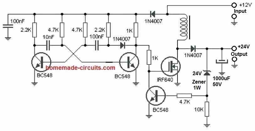
Please sir ,I am in need of a converter that can converter from 12/ to 24/48 DC to DC
Ken, you can try the following circuit. Replace the zener diode with value that you require at the output. The coil can be make by winding 100 turns of 1 mm thick super enameled copper wire over a 1 cm thick ferrite rod.
you are a priceless gift to us
What are the values of R8 and R9
In the High Current Step-Down Converter,
R8 = 4.7K, R9 = 220 ohms 1 watt
Thanks bro
Good day sir,
I always like reading your posts. Please I have a 350watts solar panel whose rating is: 42v, 8.25amps.Can i replace the TIP32 with mosfet IRF3205 for a higher current capabilty? I prefer mosfet
Thanks
Thank you Marcus, the above circuits cannot be used with a 42V input supply, 40V is the absolute maximum limit! Moreover MOSFeT cannot be used for replacing the BJT, instead a TIP142 BJT can be tried with voltage inputs below 40 V.
Please, I want to boost voltage using the IC SG3524 without transformer or any form of inductance.
It is already given in the above article.
Hi!
I have question, please write me, how can I calculate the r8,r9 resistors value in case “High Current Step-Down Converter”
I think R8 value 100-220 ohm, and r9?
Hi, R9 formula can be same as the boost converter formula:
R9 = (VIN – 0.7) * hFE / Max IO
R8 is not crucial, and can be removed or replaced with a 10K resistor.
Engineer good morning sir, please help me, I have a single 24v battery, I need a circuit to convert it to12v for my inverter please help…thanks
Hello Sunshine, you can try the last circuit from the above article to fulfill your requirement….
Thanks for your teaching, That inverter is a foreign 12v inverter, so I need a circuit that can step down 24v to 12v and handle the current, I used MOSFET 4 of 3205 in a big cooler is working but too heating..pls help..
If your inverter is a 12V inverter then you must use a 12V battery, stepping down a 24V battery to 12V would waste a lot of power and make the system inefficient.
Okay thanks sir, I appreciate..
Good afternoon sir,
My name is Johnson, from the above post I look at my inverter design and I know that the max charging safe cut off voltage for 48v inverter is 56v will it no destroy the lm/sg3524.
Hello Johnson, your SG3524 will surely get damaged at 48V, so you must use a voltage regulator for the IC. This can be in the form of a 10K 2 watt resistor and a 12V zener diode, or a switching regulator which can convert 48V to 12V.
Hi Mr Swagatam
Can you help me with a 48 Volt (45 to 55) 10 A sample charger circuit with TL494 or SG3524
let’ s say for 60 V DC input
Best wishes
Hi Cabir, the ICs you have mentioned are designed for oscillator applications, so the output will be frequency based, and this might cause slow charging of the battery.
Thank you for your very quick and highly satisfying reply
I understand that charging a 48 volt SLA for gocart car with LM3524 or TL494 chips because they are frequency based, and this might cause slow charging of the battery.
So what is your opinion about where to start
I saw your circuit “48V Solar Battery Charger Circuit with High/Low Cut-off” and read it several times I compared it with “PWM Solar Battery Charger Circuit” (as you said “frequency based, and this might cause slow charging”) also with “0 to 50V, 0 to 10amp Variable Dual Power Supply Circuit” which can be modified easily for 0 to 55V output with current control also can be used on both sides, I mean my battery could be charged with -48 volt like “48V Solar Battery Charger Circuit with High/Low Cut-off” also (I dont know what is the difference)
So please help me with where to start from and how should I go on
Best wishes
Actually a battery charging just requires a couple things to ensure a safe and effective charging. The first is a full charge auto-cut off and a constant current input.
The 48V charger circuit can ensure both the above features without any complications.
The PWM charger on the other hand is buck converter which steps down a high input DC to a lower output DC with minimum losses. This process requires a frequency which is supplied by the TL494 IC. Subsequently this frequency is smoothed by an external capacitor.
If a frequency based design is employed then a filter capacitor can solve the slow charging problem, however that would be an overkill.
Instead a simple op amp based charger with a constant current DC input makes more sense and easier to implement.
You can the following post and choose the desired concept:
Op amp Battery Charger Circuit with Auto Cut Off
A simple power supply can be also used, if the output voltage is set just under the full charge level of the battery, in that case no auto cut off would be required.
Variable Voltage, Current Power Supply Circuit Using Transistor 2N3055
Hi Swagatam
Thanks again for your very quick and highly satisfying reply
On Wensday (8th of December) I hope I will send you what my decision is with a sample schematic
Best regards
No problem Cabir, all the best to you!
Hi, Thanks for the quick response I appreciate. Johnson
Hi
What is the difference between SG3524 and LM3524D?
In High Current Step-Down Converter design with LM3524D what are the values of R4, R5, R7,R8, R9, C0, CT and L1 for effectively charging a 12v 100AH battery from a 200w solar panel with very low current?
Does any other thing need to change?
Thank you for your help as I am planning to get the part tomorrow and build this so that my battery can be charged since the solar regulator is not really charging it due to very low current
You will have to calculate all those parameters using the given formulas.
Hi, wondering if you could help me here?
I’m hoping to run a racing motorbike from an 18v electric drill battery (reads 20+v fully charged) .
The motorbike has no charging system (total loss) and the ignition needs 14.4v-15v and up to 10amps.
Do any of these designs work without the battery feedback resistor?
Thanks in advance
John
Hi, the above designs are not necessary for your simple requirement.
you can add the following regulator for charging you battery effectively:
Please use a bridge rectifier circuit between the alternator and the above regulator circuit.
R2 can be determined through the following formula
R2 = battery voltage – regulator output voltage / max charging current
D1 can be a 6V zener diode, and VR1 is used for setting up the output voltage to the battery.
Hello and thank you for this great article.
I started working on this kind of circuit (Buck-Converter for solar charging) myself a short time ago and I would like to ask how are you sure that the efficiency can reach 95%?
At the same time, for a high current design, one or more PMOS in parallel (with a low RDSon and High Drain-Source current capability) can replace the Q1. (l1 has to be recalculated).
R4 can also be replaced by a variable resistor to control the output voltage.
D1 can be replaced by a Schottky diode.
Pin10 can also be used as overvoltage protection using a tl431 and an optocoupler.
This kind of circuit can also be made with several types of ICs such as the UC3843 (limited to 30V input).
Tell me if I’m wrong.
Hello, thank you for liking this article!
I never said I am sure, I only meant that 95% efficiency can be achieved in all SMPS circuits because of the ferrite based transformer which has a high permeability and minimum eddy current losses
Why should I say you are wrong??
Thank you for the answer, it’s clearer.
I was waiting for your opinion because I didn’t want to write something wrong on your site. But now it’s clearer, thank you.
Hello. You always have interesting circuits 🙂 Tell me: I have an idea to raise the voltage to the high-voltage ignition coil in a car (from 12V to 16-18V), but with a current of at least 1.5A. Will this scheme work? If not, where to look for this type? (Thank you)
Hello, thank you for liking the post! Yes you can use the second schematic and build the specified step-up converter. You just have to replace the 2N3055 with a TIP31, and calculate the rest of the parameters as specified in the article….