In this post we investigate how to connect popular voltage regulator ICs such as 7812, 7805 in parallel for acquiring high current output from the ICs.
Voltage regulator chips mostly have their maximum current output specs fixed to some predetermined levels. Increasing them to a higher level would normally call for external out board transistors and complicated associated circuitry which might be difficult to configure for the new hobbyists. Connecting a few of them in parallel, possibly solves the problem.
The idea was requested by Mr.Raja.
Technical Specifications
Sir,
could i use three L 7815 voltage regulator ic in parallel, to get 15 volt 4 amps dc current from about 20 volt 5 amp dc source?
Sir, as LM 338 and their equivalent ic s ( which gives 5 amps ) are not available in my town. I planned to use three 7815 in parallel. Is my idea works? If so please help me.
How can i connect them in parallel ? Could i connect input of all three 7815 ic by a common wire or i should separate mutually by a diode of 2 amp? And what about out put, should i separate them or use
a common wire? And i think, i can connect the negative terminal of ic with a common wire. Is it? Please guide me.
Solving the Circuit Request
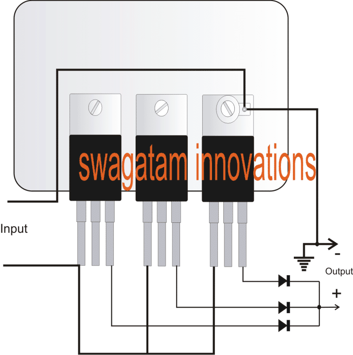
Although not recommended by many, the issue can be handled simply by connecting the regulators in parallel, as shown in the following diagram.
Here we can see the terminals of the all the three ICs connected in parallel except the output pins which are terminated with individual diodes.
However the above connection might face a crucial drawback. Since all the ICs wouldn't have precisely identical characteristics and specs could vary with their current limits, and ultimately lead to one of them supplying greater amount of current than the other, and overheating in the course.
Although this won't pose a threat to the ICs as these are always thermally protected from inside, it's never a good idea to have a semiconductor device sizzle unnecessarily.
The issue can be very easily tackled by connecting the counterparts over a common heatsink, as shown in the diagram below.
Since the tab for the ICs connect with their identical common leads (ground lead), doesn't need any sort of isolation in the form of mica isolation kit etc.
Just make sure to put them over a common aluminium plate, and then you can relax as the heat dissipation across the plate would result in correct transition of heat enabling each one with an equal share of current at their respective outputs which in return would result in an optimally combined higher current outputs, as required.
Circuit Diagram
High Current from IC 7805 using 2N3055 External Transistor
Although using 7805 or 7812 ICs in parallel is a good way of getting an enhanced current output from these chips, a better alternative is perhaps by using an external power transistor, as indicated in the following diagram:
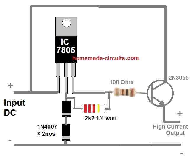
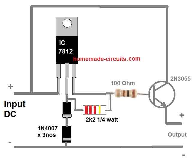
You can get as high as 5 amps from the above setup using a single 7805 IC and a 2N3055 transistor. The output will as regulated as a 78XX IC can provide. The output will be around 5 V 5 amps or 12 V 5 amps depending on which 78XX IC is used.
You can tweak the output voltage slightly by manipulating the number of 1N4007 diodes at the GND terminal of the IC.
The current output can be further adjusted by adjusting the value of the 100 ohm base resistor.


Questions & Answers
Please is it possible to produce a joule thief circuit that can use a 4×1.5v battery in parallel to produce 1.5v and 6amp and upconvert it to 12v? Please if possible how can i get the circuit?
Yes it is possible but it won't produce 6amps.
Rather its capacity will increase to 6 AH, AH refers to charge or discharge rate in terms of current in an hours time, it's does not suggest the current delivering capacity.
12v dc generator connect in a bunch on multiple input power generate and output one source
current can be increased by increasing the thickness of the secondary winding.
To decrease voltage reduce the number of turns, and to increase current use thicker wire.
It may be done for 7812, but for 7815 as proposed above the issue won't matter much.
sir
here i am looking for solar inverter,but without battery for day time purposes ,no back up required, kindly give me some idea about this circuit
Hi Vijayakumar,
What kind of load do you want to operate? please specify the load type and power, I'll try to help you with the right circuit.
thank u sir
here i am asking about residential need purposes ,like fan,light,tv.
kind regards
vijay
Hi Vijay,
I'll try to design it and post it soon in this blog.
Sir, is it possible to regulate a 12v 65Ah car battery to 6v dc and still have close to the 56Ah at the output by connecting 7806 regulators in parallel. If yes, then how many pieces of the regulators will be used. Thanks.
Yes it would be possible but you will have to use as many as 60 nos of them, instead you can use 10nos LM196 and connect then in parallel by following the conditions provided in the above article.
I'm curious to know if the spacing of, or rather the space between, the devices is crucial? Also, what's the draw of the devices themselves? By that I mean, Is there substantial current draw with not no load on the regulated volatge?
Placing them closely would help more uniform heat sharing so it's recommended. Current consumption of each IC could be around 3mA
Sir, the maximum input voltage of LM78XX series is 35v. In order to handle higher input voltage, say 80vdc/10amps, what circuit would you recommend using a simple transistor design?
Jusi, presently I have the following design which could be modified for getting the specified outputs:
https://www.homemade-circuits.com/2012/01/how-to-make-versatile-variable-voltage.html
Hello Sir,
output of TWO different LM7812 can be connected in series, so that 24vdc output is possible? If that possible how do I connect?
hello kaustubh,
that's not possible, you can try adding a 12V zener in series with the ground terminal of the IC and a 1K resistor between output and ground pins to achieve the same…or simply replace the 7812 with a 7824
Hai genius…
The 3 7812 using…
It will provide 3 ampere or not
Hi Kesava, yes it will allow you to get 3 amps max
Hai sir….
1.Using 3 7812 it will provide 3 amps
2.3 ampere or 6 ampere Diode we want to use…
3. I need output 12v 5 amps..shall i use 5 ics…..
Pls help me sir
for 3 amp you must use 6amp diode (6A4), for 5 amp output you may have to incorporate 6 to 7nos of 7812 in parallel.
Hai sir…i have 3 doubts…
1.I use 7812 and 7805 both working good…7805 is using for 555…
7812 is using for Relay….
Sometimes relay working good…Sometimes not working when i check o/p volt of 7812 it showing 1.2…
What i want do….sir…
Pls help me sir
Kesava, your 7812 could be faulty or not connected properly, check its connections or simply change it with a new good quality IC
Thank u sir….
But i replace it new one sir ….stil same problem….when i disconnect the relay ..7812 o/p ..11.9 showing correctly….when i connect in relay it will show 11.7….when i activate the 7805 ic….the 7812 will varying voltage automatically…..till now i can't able to find solution….now I'm using zener as a regulator….pls make it any solution….sir
Kesava, connect the IC 555 with 7812 and check the response….7805 is actually not needed.
Hai sir…
For smartphone mobile charging….shall i use 2 7805 in parallel….o/p using two 3 amps diode 5408….it will provide output 5v 2 amps sir….
For mobile charging input voltage of 7805 I'm uing 6v 4.5ah battery …it will be okay sir….
yes it will do!
adding 5408 diodes will drop 0.6V from the 7805 which could create problems in charging. instead you could try adding an outboard transistor to raise the current as shown here
https://www.homemade-circuits.com/2012/05/dc-to-dc-double-cell-phone-charger.html
Thank u sir….
It is actually not that simple. Thicker secondary will indeed allow greater current capacity, will lower the heat losses becaue of lower resistance but to actually get more juice out of that transformer the primary might need to be rewound; please take note that the current in the primary will increase accordingly. Also the limited crossection of the core might not allow more flux between the windings. If it's a classic E-I laminated core it also performs heatsinking function to some extent especially for primary that is deep burier.
sir same basese pr maine ek circuit banai h 12v390 watt solar panel h mere pass or maine 7815 use kia h 25 nos jisse mai 2 fan 1light use kar raha hu without battery first time regulator ic ko parallel krne me confusion thi but amp check kia to maza agaya ????????????
Hi Shiraz, Happy to know it’s working as per the requirement!!
Hello
Excuse my English
I have a small solar panel 1.12 (A) maximum power current 17.82 (V) maximum power voltage
I would like to connect a 5w dc12v led lamp. Can I plug in directly or do I need 1 ic regulator and 1 transistor
Thank you
Regards
Hello, you will have to use the following design in between the led and the solar input
For the resistor you can use
R = 1.25 / 0.4 = 3 ohm 1 watt resistor
thank you.
i will do what you say
Hi Swagatam!
It’s Great! You endorsed use of parallel 78xx ICs with individual isolation diode at output and a common heat-sink. Simplest! And I do the same! However, out of two 7812s I use to get 2Amp, one is hotter than other and my 12v stereo amplifier gives humming noise. Input is 15v 2Amp full-wave Diode bridge rectification with ripple suppression with 4,700uFx2 35v capacitors. Kindly help. Regards.
CT
Thank you CT. Did you connect the ICs over a common heatsink? You must mount all the ICs close to each other over a common aluminum heatsink, then the dissipation will be uniformly shared across all the ICs and no single device will become hot alone.
Thanks Swagatam.
IC uneven heating is taken care of with common heat-sink, thanks. But, the main issue is HUM created due to 7812s. 1. All requisite components of Stereo kit are properly grounded with chassis. 2. No HUM when 7812 not used (Direct higher voltage 15v is applied to amplifier kit for a few seconds for verification only of HUM). Any solution? Regards & thanks in advance!
You are welcome CT, In that case I think you can try putting some decoupling capacitors across the output and input terminals of the ICs with respect to ground. You can also try grounding the heatsink with the chassis of the amplifier. For the capacitors you can try attaching 100uF/25V, and 0.1uF across the output/ground terminals of the Ics, and repeat the same across the input pins, see if that helps. Try putting the capacitor very close to the IC pins.
Hell Sir Swagatam
Would be very glad if you kindly tell me that if this method is practical with 2N3055 for getting more current or it needs some changes in circuit diagram’s planning.
Wish you health and success
Very truly yours
Hello Najieh, yes that’s possible. You can as many 2N3055 as you wish to accomplish the desired output current. Just make sure to add a small resistor in series with the emitters of each transistor
More info is provided under this article:
Connecting Two or More Transistors in Parallel
Hello dear Sir Swagatam and thank you very much for so soon reply and valuable article you suggested.
Wish you all the best
Very truly yours
You are most welcome Najieh.
Hi Swagatam;
Please advise according to the followings; If:
a) 7809 input voltage 24 volts
b) 7812 input voltage 24 volts
so; in which values we should prefer capacitors between input leg and gnd and also between gnd and output leg. And capacitors should be bipolar or not-Thanks
Hi Suat, if the voltage regulator IC is very close to the bridge rectifier and filter capacitor of the power supply then no need to add those capacitors.
Sir I read your answer are very easily and informative and useful I shall get guaidline to you thanks so much
Thank you Abdullah!
I am thankful for your informative presentation.. I will try both in my power pack design
No problem, let me know if you have further questions.