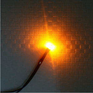
In this post I have explained a simple 220V mains operated transformerless single rice bulb power supply circuit, which may be used for illuminating electronic rice lamp diyas replacing traditional oil lamp type diyas during festivals or for decorating sacred idols. The idea was requested by Ms. Rashmi.
Technical Specifications
I want to make a rice light LED bulb with a long wire. I want to change my oil lamp to LED lit. Pls help me make a single rice LED tiny bulb connected to a long wire with a plug in the end.
I want to connect it to my 440V power point at home. So what kind of adapter/transformer can I use. How much will it cost me approx!?
Any 12V bulb, may it be a rice bulb or other forms can be simply lit through a 12V AC/DC adapter rated as per the specified bulb current requirement.
Therefore according to the request a rice bulb too can be powered via a 12V/500mA or 1amp AC/DC adapter.
However the current requirement of such bulbs being too small the above type of power supply could look bulky and costly (approx Rs.100/- in India).
An alternative suitable, compact mains power supply for illuminating it could be implemented through a capactive type of power supply, the making procedure is I have explained below.
The Design
A rice bulb could be an LED or in the form of a tiny incandescent lamp rated to operate at 6, 12 or 24V AC/DC, with current consumption of typically 50, 30, 10mA respectively.
Here we use a 12V rice bulb which may consume a current at around 25mA.
We have seen many exclusively designed transformerless power supply in this blog, one of them has been employed here or driving the proposed single rice bulb diya at 220V or 120V mains supply.
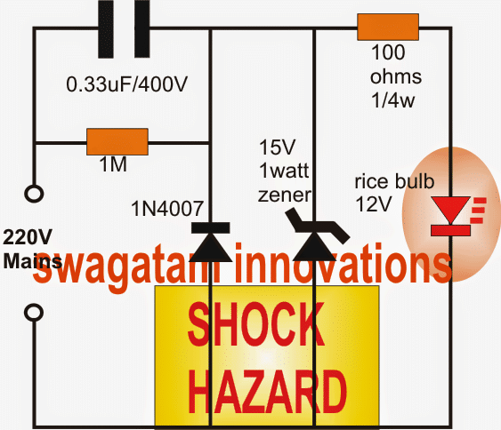
Looking at the circuit diagram below, a straightforward half wave capacitive power supply can be seen configured for driving the attached single rice bulb.
The 0.33uF capacitor is positioned for dropping the mains 220V current to the desired low value level as per the lamp specs.
The 1N4007 diode takes the sting away from the switching initial surge current by grounding one half cycle of the mains and allows only the positive half cycle to proceed toward the lamp.
The 15 zener diode further makes sure that only 15V reaches ahead across the lamp, while the resistor helps to keep the current from rising to any higher dangerous levels.
The capacitor 0.33uF may be tweaked a bit if the lamp intensity does not produce the desired illumination, other higher values such as 0.47uF. 0.68uF or even 1uF may be tried in place of 0.33uF for the same.
Alternatively a 100uF/50V capacitor may be connected across the zener diode for obtaining the above optimization.
The entire circuit is directly linked with LETHAL mains potential, and therefore is extremely dangerous to handle without adequate insulation while switched ON. Due care is advised.
Circuit Diagram


Questions & Answers
sir, namaskaar mere paas ek 12v,10w bike indicator filament type bulb hai jise main transformer less circuit se operate karna chahta hoon. kripya koi circuit diagram send kar dijiye aapki ati kripa hogi.
Ashu,
You can simply connect a high value non polar capacitor in series with the 12V 10 wa bulb to illuminate it from 220V AC.
If you divide 10 by 12 we get 0.833 that means we will need around 800 mA current to illuminate it.
Since a 1uF/400V produces around 50 mA current, you will require around 16 uF / 400V capacitor to illuminate your bulb.
Please buy a 16 uF / 400V PPC non-polar capacitor and connect it in series with your bulb and 220V mains AC.
REMEMBER THIS CIRCUIT WILL BE EXTREMELY DANGEROUS TO TOUCH IN OPEN AND POWERED CONDTION, MAKE SURE TO INSULATE IT THOROUGHLY BEFORE TESTING AND HANDLING IT.
Sir,namaskaar 100 ohms resistor iss circuit mein kyon rakhi gayi hai iska load ke hisaab se Maan kaise nikale aur kya ye resistor surge resistor hai.kripya vistaar purvak bataye aapki ATI kripa hogi.
Hello Ashu, the formula for calculating the LED resistor is:
R = (Zener V – LED forward voltage) / LED current.
This is a current limiting resistor for the LED.
Sir, namaskar uppar diye gaye circuit mein R2 resistor ki Maan kis prakaar nikale aur yadi load change karein toh kaise R2 ko badle
Hello, which R2 are you referring to, I can’t see any R2 in the above diagram?
hi,swagatam sir. kya main iss circuit mein 3v,50ma torch bulb istemaal kar sakta hoon.
Hi Atul,
haan kar sakte ho, but you will have to replace the 15 V zener with 4.7 V zener.
can you explain why it will gives a shock??
Hi dude, give a try to build up and touch it, better to prove it than ask
hi sir what is the max output current of this circuit
20mA