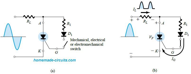
In this article I have explained many interesting SCR application circuits and also learn the main features and properties of an SCR also called a thyristor device. What’s an SCR or Thyristor SCR is the acronym of Silicon Controlled Rectifier, as the name suggests it’s a kind of diode or a rectifying agent whose conduction […]
Newly Updated Circuit Projects:
How Varactor (Varicap) Diodes Work
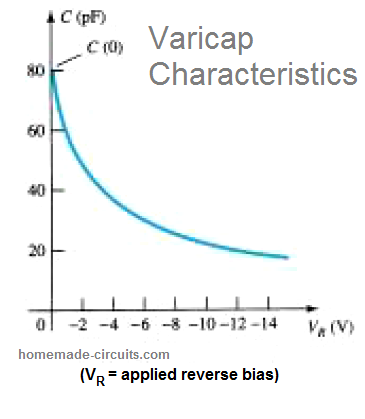
A varactor diode, also called varicap, VVC (voltage-variable capacitance, or tuning diode, is a type of semiconductor diode which features a variable voltage-dependent capacitance on its p-n junction when the device is reversed biased. Reverse bias basically means when the diode is subjected to an opposite voltage, meaning a positive voltage at the cathode, and […]
Electronic Touch Organ Circuit
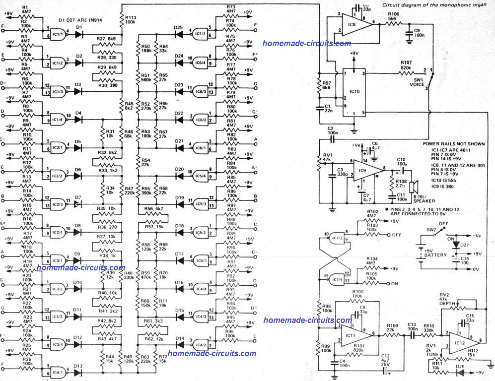
An electronic touch organ is an intriguing musical device which produces very pleasant musical notes in response to finger touches on special touch sensitive electronic pads or buttons. Modern day organs are, however, very costly which usually places these outside the reach of the majority of folks. Low cost options types lack performance, and are […]
Prevent Amplifier Fuse from Blowing During Power Switch ON
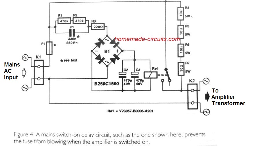
Is your power amplifier fuse blowing during power switch ON? It could be happening due to the initial high current drawn by the loudspeakers, when power is switched ON. The simple amplifier fuse protection circuits presented here can be effectively used for solving the issue. The problem is commonly seen in high power amplifiers, where […]
LED Obstruction Light Circuit
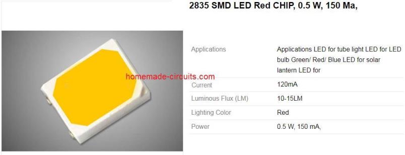
Obstruction lights are warning lights that we see at the top of tall structures like towers and skyscrapers, installed for indicating the aircrafts and other flying objects about these obstructions. These lights alert the flying aircrafts regarding the minimum height they should maintain above these tall structures to avoid a possible collision and accidents. Obstruction […]
Schottky Diodes – Working, Characteristics, Application
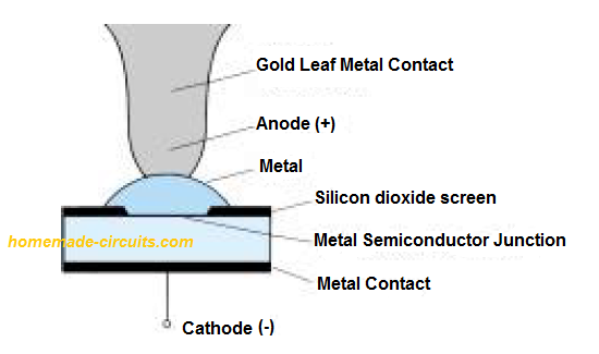
Schottky barrier diodes are semiconductor diodes designed with minimal forward voltage and fast switching speeds which may be as low as 10 ns. These are manufactured in current ranges of 500 mA to 5 amps and up to 40 V. Due to these features they become specifically suitable in low voltage, high frequency applications such […]