A triac based battery charger replaces a normal relay for automatically cutting off power to the battery very efficiently.
In this post I have explained a simple a battery charger circuit using a triac auto shut-off facility. The circuit can be used for charging any high current, high AH types battery with a full-charge auto cut-off feature.
The idea was requested by Mr. Rakesh Parmar.
Using Triac Instead of Relay
In one of the earlier posts I have explained a high current battery charger circuit based on a relay total shut off concept, which used a relay to initiate the charging process by switching ON the mains to the transformer and then shutting off the mains as soon as the full charge level was reached for the
battery.
In the proposed triac based battery charger circuit the operational principle is exactly similar except the incorporation of a triac instead of a relay.
Circuit Diagram
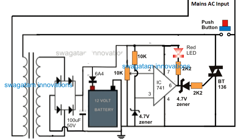
When mains power is applied the circuit does not switch ON by itself, and remains in a standby position.
The indicated push button is positioned for initiating the charging process, therefore as soon as this switch is pressed the triac ismomentarily shorted allowing the transformer to access the mains power
for that instant.
The above action also instantaneously allows the circuit to get powered for that particular period of time.
How it Works
Assuming the battery to be in the discharged position, the above initialization causes a voltage to appear at pin#2 of the opamp at a level lower than the referenced pin#3 of the IC.
This in turn causes pin#6 of the opamp to go high, activating the triac and also latching the transformer in the powered position.
The entire circuit now gets latched and powered even after the switched is released, providing the required charging parameters to the battery. The red LED illuminates confirming the charging initialization of the battery.
As the battery gets charged, pin#2 potential gradually begins rising, until when finally it goes above the reference level of pin#3, which immediately prompts the output of the IC to go low. The moment this happens the triac gate trigger gets cut-off, breaking the latching action, and the entire circuit gets switched OFF.
The circuit returns to its previous standby position, until the next time when the switch is pushed again
for a new caging cycle.
If you liked this battery charger circuit using triac, please do share it with the others.



Questions & Answers
Hi Swagatam;
My battery charger output is 88V 8.5A, I would like to drive it with the item which is 16A and higher than 150V. I will not use relay, so which one you would avise mosfet or triac?
Hi Suat, Since your charger output is 88V DC, so a TRIAC cannot be used because it does not turn OFF with DC. You must use an N-channel MOSFET rated at minimum 150V (preferably 200V) and 16A or higher. A 200V 30A MOSFET with proper heatsink would be a safe and reliable choice.
Thanks Swagatam. I will use pic c to control the cirucit which is able to generate – pulse waveform by using the NPN tr. So, is it possible to turn OFF the triac?
Hi Suat, no even with PIC control the triac is still operating with a DC supply, so it cannot be turned off, unless the MT1/MT2 supplies are turned off…
Sir, what modifications can I make to the triac battery charging circuit to make to charge 24v battery.
Sunday, just replace the transformer with a 24V transformer and replace the opamp with a LM358 opamp…that’s all.
hi sir,
can I connect the point where the switch to be pressed is situated permanently together. so that the circuit can keeps operating without anybody initiating the power ON of the circuits.
I want it working on its own whenever the op amp sense the voltage to be low to charge and switch off whenever it reaches its desired voltage.
if it cannot work like that, what adjustment to be make.
thanks.
Sir, what then can I do to make it work at any point in time whenever there is mains input supply and someone is not available to be switching ON that switch all the time. So the circuit can reset itself whenever the needs be.
Also, what is to be done or any adjustment to be made to make the circuit charge a 24 volts battery.
Thanks.
Sunday, If you want a self regulating battery changer then you may have replace the triac with a mosfet, as shown in the following example:
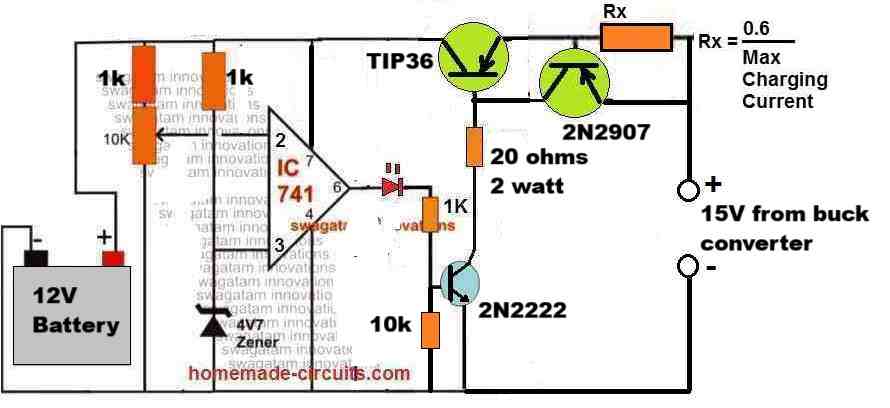
for 24V just replace the transformer with a 24V transformer and replace the opamp with a LM358 opamp…that’s all.
Hi Sunday,
If you short circuit the reset switch then the automatic cut off will never happen, so it is not a good idea to do that…
iff somebody will charge the car batery directly on the car, the main will be on the car chassis!!!?
Sir, kindly suggest me a circuit for 4p3s LI ion bty.
Battery Ratings with are: 12v, 10 Ah.
Much needed circuit for me searching for a long time. Plz help.
Hello M.Ahsan,
You can use the same circuit as above, the current rating for the transformer would be 12V, 5 * 4 = 20 amp.
You can use a 1000u/25V filter cap instead of the shown 100uF
Sir, I have 4P3S LI ion bty =
12v 10 Ah bty. Can I charge this LI ion bty with this cct? And what is this cct’s o/p Current. Sir plz guide.
Hi M. Ahsan,
yes you can do it, just make sure to use an input transformer current that’s around 50% of the battery mAH.
Sir u mean 5 amp transformer ? If 10 Ah bty. And what will be the o/p of the cct if I use 5 amp transformer?
Yes, 5 amp would be ok for a 10 Ah Li-Ion battery.
With an ideal 5 amp transformer, the output too battery would be 5 amps…
But sir BMS with 4p3s is taking minimum 2.5 A. 5 amp is’t too much?
I am assuming each battery is rated at 10 Ah, so 4 in parallel makes it 40 Ah, 50% of 40Ah is 20 amps, 20/4 = 5 amps.
What is the exact Ah rating of each battery?
hello master. Can smps adapter be used instead of transformer? If yes, can you share the wiring diagram?
yes any DC power source can be used!
Dear Swagathan, Is there a way to modify the circuit to work in an auto mode. I mean, that will not require any momentary push of the button. The circuit will sense again that the preset low voltage level of the battery has been reached, therefore starts up the charging process again. If there is, then it can be used in inverter.
Similarly, how can one sends to this forum or yourself “a suggested personal circuit diagrams on any of the topics open for discussion on the forum for improvement and further modifications”. I could see that, there is no attachment icon.
Hello Abiola, you can do it simply by replacing the push switch with a wire link. You can post the diagram on any free image hosting site and send the link here.
Hi Swagatam, as i’m reviewing the circuit in diagram one of the AC line (220/110v) connected to Push Button and ground of the circuit? Please help me sir. Thanks
Hi Eric, that’s correct. The push button momentarily connects the transformer primary with AC input. This initiates the op amp and switches ON the triac. Once this happens the triac overrides the push button and the circuit latches ON, until the battery is fully charged, when the triac switches OFF resetting the system to its initial position.
Hi Swagatam, the triac Bt136 was damaged immediately when connecting AC. Maybe i got error right? But i did the circuit same as diagram.
Hi Eric, It could be due to an error, or an bad quality triac, or due to the back EMF from the transformer winding.
Try a higher rated triac, may be a BTA08/800V
https://m.littelfuse.com/~/media/electronics/datasheets/switching_thyristors/littelfuse_thyristor_bta08_600bw3_d_datasheet.pdf.pdf
As you see the only load on the triac is the transformer primary, so it’s impossible for a good quality triac to burn in this condition.
greetings, your material is first line, very good, I want to know the cause, why the load starts automatically without using the button, I think it is because of the positions of the triac pins mt1 and mt2, I predict that when inverted, the circuit is turned on without using the button, otherwise we must consider Edwin’s comment where it is corrected, and the second option is given, since in one of the terminals it remains continuous with the triac chassis, I would like to know if the chassis of the triac is continuous with earth or goes with the other, if it is the second option because I assume that the triac remains active, since I made the mistake of using the button and the operational one is damaged.
Hello John, the diagram is already corrected, and in this corrected version there’s no chance of an accidental triac switch ON, unless the opamp output generates a spurious voltage leakage.
The ground symbol does not indicate chassis connection, it simply indicates the negative supply line of the circuit. By no means this line must be connected to the body or chassis of the enclosure, which could otherwise create a catastrophic situation and short circuit.
To avoid any chance of the triac misfiring you can connect a 10uF capacitor across its gate and the ground line.
Can I use a Transformer from a 650V UPS for this project?
…and one more thing to note is that the LED/resistor must be across the output of the opamp and ground line…not the positive line.
Thank you for pointing out the mistake Wale, I have corrected the diagram, please check it.
Abiola. Mr Swagman, please review the connections at the led, 2.2k and the op op amp output. Ac voltage should not comes there at all .review it.
yes you can, include a 24V truck headlight lamp in series with the positive to limit the current to a safer level….