A very simple mud or soil moisture tester circuit can be built by using a single opamp and a few passive components, I have explained the details through the following article.
Circuit Objective
After water and sunlight the earth or the soil is the next most important natural gift that this planet has provided us with, without which persisting of the living beings could never be possible.
Soil produces plants, and plants supply us food. However plants need a well watered soil, or in other words plants or crops cannot survive without an optimal supply of water to the soil in which they grow.
Therefore testing the correct soil moisture becomes a crucial aspect in order to cultivate healthy crops without wasting excess water.
A simple soil moisture tester circuit explained can be used by anybody who may be interested to check or monitor the moisture level of a given area of land and ensure the correct amount of water supply to it, either manually or automatically through the same circuit.
So we have both the options available with this circuit, it enables the user to test the level of moisture of the soil, and if required make the unit an automatic soil moisture level controller by connecting a motor pump with the attached relay contacts in the circuit.
Circuit Operation
Let's see how the circuit is designed to function:
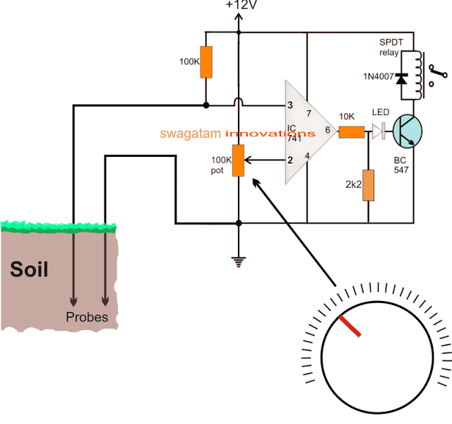
Referring to the circuit above, the design makes use of a single IC 741 opamp comparator for the required testing function.
The pin3 which is the non-inverting input of the opamp is used as the main sensor probe with respect to the other probe connected with the ground.
The moisture level present in the soil develops a resistance across it which increases with a decrease in the moisture level and decreases with an increase in the moisture level, meaning a wet soil will have a much lower resistance compared to a dryer soil.
This aspect is exploited in the design the probes are used to test the soil resistance between pin#3 and ground of the comparator IC 741.
This soil resistance forms a potential divider with the 100K resistor connected across the positive supply line and pin#3 of the IC, and the potential difference developed here in response to the soil moisture level is compared by the potential at pin#2.
Pin#2 potential is determined by the setting the shown 100k pot. Thus this pot is effectively used for determining or verifying the exact moisture present in the soil.
If the soil moisture produces a lower resistance at pin#3 than the set level at pin#2, the output at pin#6 is rendered low, meaning when the soil is relatively wet the output of the opamp shows a zero volt, while in case the soil condition develops a higher resistance (dry condition) then the output of the opamp goes positive, triggering the connected transistor and the relay.
In other words, the output of the opamp and the relay stay switched OFF as long as as the soil moisture level is more than the threshold set by the pin#2 pot, and vice versa. Therefore a relatively wet soil will keep the relay switched OFF, and a dry soil will switch it ON.
The LED complements the relay action and illuminates whenever the soil is dry than the desired set level.
This pot needs to be appropriately calibrated with a dial and then the various points across the dial marked as per the predetermined moisture content of a sample soil collected inside a container.
Once this is done, the calibrated pot can be used for checking any soil by simply inserting the shown probes into the soil, and by adjusting the pot until the output is rendered a high (LED ON).
How to use the Circuit as a Soil Moisture Controller
As explained above, once the pot is set to a desired value, whenever the soil moisture goes below this set level, the relay is instantly activated.
In the switched ON position the relay contacts join the N/O contacts, and these contacts could be wired to a water pump and its power supply in series, so that whenever the relay clicks, the motor pump is activated and the soil begins getting the required water supply until its moisture level is restored to the desired optimal point.
At this level the opamp detects the condition and quickly changes over to a zero logic at its output, switching OFF the relay and the motor, the water spraying is consequently stopped.
The above action keeps repeating by testing the soil moisture and applying water accordingly, in an entirely automated way without any manual intervention.
Using Iron Nails as Probes
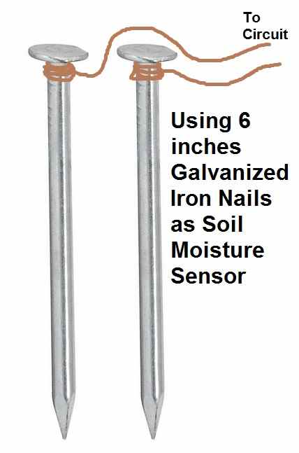
For the sensor probes you can simply use a pair of good quality galvanized iron nails which can be around 6 inches long, as shown in the following image. Solder the sensor wires from the op amp circuit with the nails and push the nails at least 5 inches deep inside the soil. Make sure the distance between the probes is not more than 3 inches wide, inside the soil.
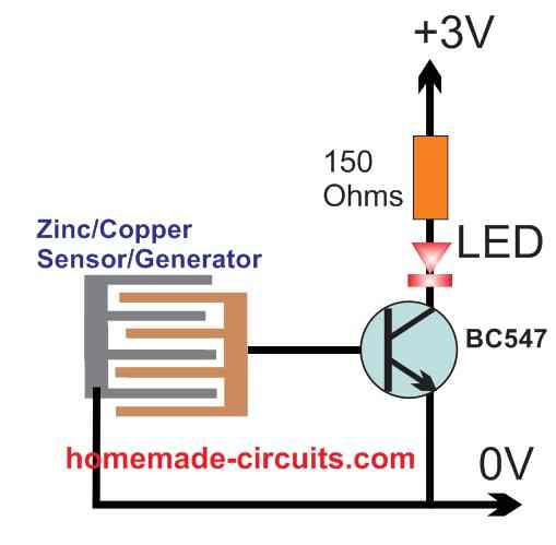
Moisture Sensor using Copper/Zinc Mesh which works like Electricity Generator
The idea was suggested by one of the avid readers of this blog, Mr. Doug:
I have what I suspect is an impossible circuit, but want to run it pass you to confirm.
I am sure you have knowledge of a simple moisture tester. This device uses dissimilar metals generally made up of copper and zinc. These metals when exposed to moisture (water) give a very low electrical current, this is the basis of my question:
I would like to know if there is any circuit and or device that could be powered by say a 3.7vdc lithium Ion battery or a 1.5VDC AAA battery that is basically in the off position, until two leads senses moisture, thereby powering up and indicating by a low volt LED that there is moisture across these 2 “LEADS” dissimilar metals but wouldn’t cause any, “shock” if applied to sensitive skin?
Soil Moisture Sensor with Motor Pump Control
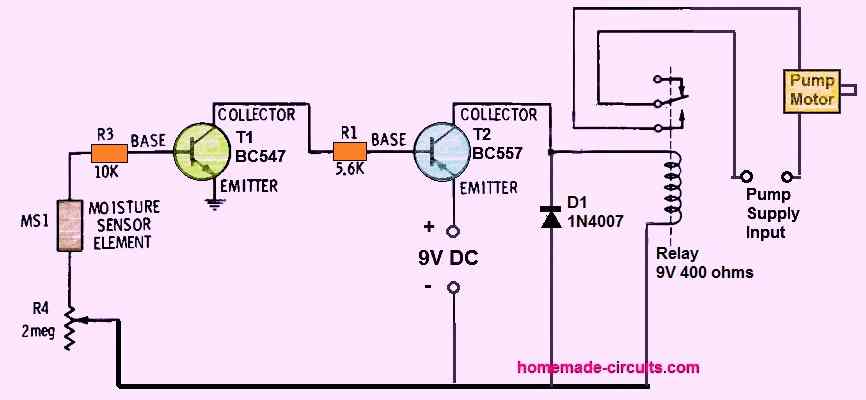
The previous circuit using a single BC547 can be further upgraded into a soil moisture controller circuit with motor pump.
The moisture element can be the same as used in the earlier diagram, consisting of zinc/copper tracks held very close to each other.
As long as there's no moisture in the soil, or the soil is dry, no voltage is fed to the base of the BC547.
Due to this both the transistors are switched OFF, causing the relay to remain switched OFF.
Since the motor pump is connected across the N/C contacts of the motor, the motor pump remains switch ON, so that water can be released into the soil.
When moisture or water droplets is detected across the moisture sensing element, tiny electrical potential is generated across the sensor terminals.
This tiny potential difference is sufficient to trigger ON the BC547 transistor which in turn causes the BC557 to switch ON hard.
The BC557 now turns the relay contacts OFF, which was normally switched ON due to a dry moisture sensor detection.
The relay contacts switch OFF the motor pump. The pump remains OFF as long as the moisture sensor does not become dry again.
The moisture sensor can be inserted deep into the soil whose moisture content needs to be sensed and controlled through the motor pump water.
The pot R4 can be used to adjust the sensitivity of the moisture sensor element.



Questions & Answers
Hello again thank youu for your reply , im doing a watering system for my circuit project we can only use op amp 741 im trying to do first the water level detection using 3 op amps 3 leds but i want to add a water pump i have a 3 to 5 v submersible water pump to it that turn on when the water is only at the lowest level is there really no way to do that using op amp 741 with a relay or something
Where will you use this circuit, for watering the soil and the the plants?
hello how to do automatic 3v water pump using op amp 741 on a pcb how to add awater indicator to it
and thank you for your help your a hero
Hi, unfortunately the IC 741 cannot work with 3V supply, so I think 741 cannot be used.
Hi, is there a way to have 2 LED and 1 Buzzer which will indicate the dry moisture level as your circuit only has one LED which lights up when the moisture level is high (low output) .
That’s possible! In the first circuit, remove the existing LED, the transistor, the 10k, the 2.2k and the relay.
Now a connect an LED between the pin#6 of the op-amp and the positive, and another LED between pin#6 and the ground.
Both the LEDs must have a 1k resistor in series.
After this, connect a buzzer between pin#6 and either positive or ground.
Sir can we use LM 1/4 324 insteadof ic 741.
yes you can!
Hi Swagatam
I hope I find you well, I wanted to ask about how long should the leads to the electrodes be? can they be placed far apart inorder to water a fairly large field?
Hi witness, The length of the probes will depend on how deep you wish to test the soil. To increase the distance between the probes you may have to increase the resistance at pin3 appropriately, may be up to 2M2 or more.
Hello mr. Swagatam good evening. Can I ask a favor how to make (AVR ) automatic voltage regulator for my refrigerator? Please ✋. Thank you so much ❤️????
Hi Mark, you can try the following design, this should do the job
https://www.homemade-circuits.com/how-to-make-small-homemade-automatic/
Sir, what is the function of the op amp in this circuit?
It is a comparator:
https://www.homemade-circuits.com/comparators-using-ic-741-ic-311-ic-339/
sir, Which relay you are going to use in this circuit? it is a 6V relay or something else?
can you please tell me how you connect relay?
Himanshu,
since the supply is 12V, therefore the relay is also 12V. You ca get more info here:
https://www.homemade-circuits.com/how-a-relay-works-in-circuits-how-to-connect-it/
Sir, did you get my message?
What's that 2k2 ohm resistor in the circuit diagram sir? Is that a typographical error? What should it be? 22k ohm or 2.2k ohm resistor? I hope i could get a reply from you ASAP because I am needing this in my project to be submitted next week. Thank you very much sir!
Andrea, 2K2 is another way of writing 2.2K
Sir I Want To Drive A Relay From getting Easy Signal From Ultrasonic Sonar. Abmnd i want to make a easy Circuit. Not Complex
Please Help ame Sir
Sharoj, it will be a complex circuit as far as I think….cannot be an easy one.
https://drive.google.com/file/d/0B8k3jWgWe95XTXU3NERYQ0UxZk0/view?usp=sharing
My Alarm Circuit Work on 9v Battery. And Have a mini Speaker In this Circuit.
I want to replace The Speaker And Connect the Cable To my Speaker.
you can do it…
stainless steel rods
Sir Can You Please Provide Me Simple Microphone Amplifier Circuit
Sharoj, presently I do not have in my website, but you can find many such circuits online.
can you show how a mini 12v pump can be integrated with this circuit to water plants that are in pots?
the relay connections will be similar to the following circuit:
https://www.homemade-circuits.com/2011/12/how-to-make-simple-water-level.html
Sir I Am Sorry I Couldn't Clear You . Actually I Want To Connect A Speaker with My Siren Out Put . nowadays In Market Very few Speaker Are Selling Called Mobile Phone .
Thank You Sir
please put the image on "sharing" mode, because I am not able to be see it at the moment.
https://drive.google.com/file/d/0B8k3jWgWe95XTXU3NERYQ0UxZk0/view?usp=docslist_apiir My Alarm Circuit Work on 9v Battery. And Have a mini Speaker In this Circuit.
I want to replace The Speaker And Connect the Cable To Mini Speaker.
Sharoj, show me your siren circuit then I'll tell you how to fix a volume control
Sir Please Help Me How Can I Control Bolume ??? Sir Please Describe Me .
add a volume control to the system and then slowly increase it, if the speaker distorts then its too high for the speaker
How can i understand the Adjustment ? Is my speaker okay for Received signal from siren out . my siren ciruit work in 9v
if the siren signal is already amplified then make sure the sound box speaker is rated to handle the siren wattage.
If you have an amplifier inside your soundbox then there will be no problem…you can go ahead with it.
If not then use an amplifier in between the sound box and the siren input
Sir
Actually I Want To connect A Sound Box With my Siren Out Put. Then my soundbox willget damage ???
sorry, I still did not understand your requirement, do you want to drive an external speaker by providing a music input from your cell phone? in that case you will require an amplifier in the middle.
Dear Sir I Want to make An Circuit That I can Easily Connect A mp3 out to A Mobile Speaker In . But Sir I Am Afraid If The Mobile Speaker Get Damage ?? Sir please Help Me
Dear Saroj, it is not possible to use the mobile speaker with an external music input and this is not recommended.
…there's no external port in mobile phones which will allow it to connect with external inputs
Sir, why relay in my circuit can’t switch off?
I have measured the relay voltage on amperemeter when the probe is connected to wet soil, and its value is 4V, not to zero volt so the relay can’t switch off and the motor always on when the soil is dry or wet
You can remove the 2k2 with the LED included.
we are not able to measure minute difference in moisture. can you help us to resolve this.
you will have to use an Arduino for minute measurements:
https://www.homemade-circuits.com/digital-temperature-humidity-meter/
Aini, Did you connect the LED shown at the base of the transistor, what is the response of the LED?
Yes I have connected the LED at the base of the transistor. The response is when the soil is dry, LED on. And when the soil is wet, LED off. Is that correct?
Yes that’s correct.
So when the LED is OFf, the base/emitter voltage will be zero and the relay must be completely OFF…please check and rectify this so that your problem is solved