The simple programmable humidity sensor circuit I have explained in this article can be used for controlling or maintaining a suitable level of humidity inside a close premise.
The circuit could be used in poultry farms or similar areas where humidity level becomes crucial for keeping the animals healthy. The idea was requested by Mr. Tanvir
How it Works
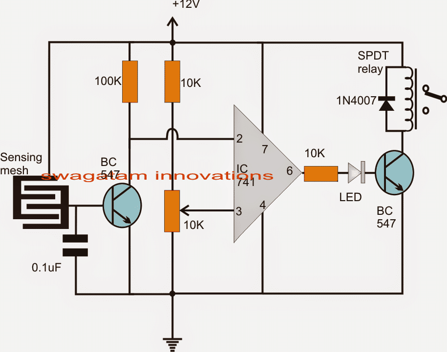
Referring to the proposed humidity sensor, controller circuit, we find the design to be dependent on a single opamp module configured as a comparator.
Pin3 of the IC which is the non-inverting input of the IC is held with a predetermined reference level set by the 10k preset.
Pin2 of the IC is held at the supply potential via the 100k resistor.
This pinout is also connected to the collector of an NPN transistor.
The base of the NPN is connected to a conductor mesh separated by another mesh which is connected to the positive supply of the circuit.
The separation of the two meshes are optimized over a close proximity such that the humidity content is able to bridge the gap sufficiently during optimal levels and vice versa.
When power is switched ON initially, the humidity is allowed to increase in the premise by spreading water through a very fine water sprayer. This is done through a device connected to the relay of the circuit in the N/C position.
As the humidity increases depending on the level of humidity and the setting of the 10k preset, the base of the NPN transistor tends to get saturated and in case the level exceeds the predetermined threshold the transistor conducts.
This pulls and brings pin2 potential toward ground level.
The above action allows pin3 of the IC to attain a more positive potential than at pin2, prompting the output to become high.
The high output now triggers the relay driver stage, switching OFF the connected water sprayer.
As long as the humidity level within the area stays above the set threshold, the relay holds its position and keeps the sprayer switched off.
However the moment the humidity level tends to get lower below the required point, the operations are instantly triggered and repeated making sure that the humidity level never gets too low or too high inside the chamber.
Circuit Diagram
Sensor Specification
The sensor can be made by etching a copper clad PCB in the following manner:
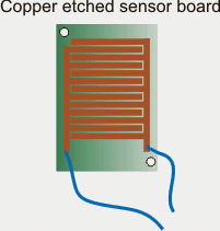
Using Glass as the Sensor
The copper mesh shown above seems to have a drawback, the moisture trapped within the copper lines could turn into water droplets and clog the mesh causing a permanent switch ON for the relay.
A smarter way of sensing moisture could be by using a glass and an LDR for the detection. To implement it practically with the circuit, the following changes could be made in the above design.
1) remove the BC547 transistor and its base componets.
2) connect a refernce zener across pin#2 and ground.
3) replace 10K with a LDR, and configure an LED and a clear glass such that the light from the LED falls on the LDR through that glass.
Now as long as the mositure level is low, the glass stays clean and allows maximum light for the LDR causing the relay to switch ON and spray the mist.
As soon as the moisture level increases above the set threshold level, the glass gets obscure enough causing pin#3 potential to fall below pin#2, and switching OFF the relay, until the glass again becomes clear.


Questions & Answers
Bonsoir, si on essaye de remplacer le capteur décrit dans ce circuit par un capteur conventionnel d’humidité est ce que le circuit peut fonctionner?
Hi Jiseph, yes, you can replace the shown mesh sensor with any standard humidity sensor module….
Sir if you can make a video tutorial on the subject. it will be very helpful.
Hi Vik, A video is not required actually, because the circuit is too simple and will start working quickly once built.
I can guide you with the testing procedure and other troubleshooting if you have problems with the circuit.
sir , can you give a youtube video for this please, it’s may helpful to learn better and now a days every one need this product also.
Hi Muni,
I may try to update in my free time, however I don’t think it is required because the project is very easy and can be built and implemented practically without any difficulty. Let me know if you have any doubts or questions.
Hi sir, very very good, so can you have a youtoub tuturial video for this?
Thanks.
Joseph.
Thank you Joseph, presently I do not have youtube tutorial, if possible I will try to upload one soon…
Hello Sir,
I have just completed this project. I printed the sensor on a small PCB measuring 9 cm long and 3 cm wide. I did everything by hand. The circuit responds very quickly, even when I try to blow air from my mouth onto this sensor.
It seems to me that this very fast response, even when breathing over it, is a good thing. However, it does not allow the circuit to provide the best response when the ambient humidity level in a room is high.
My question is the following: with the PCB layout that you show in this article, what is the value of its resistance?
In other words, how can we determine the relationship between the reference resistance placed at the integrated circuit and the humidity level in the room?
Thank you.
Thank you Joseph, and glad the circuit is working for you…
The PCB layout resistance in dry condition can be many megaohms, and in moist condition it could be just a few kilohms.
When the BJT conducts it just grounds the pin2 to ground, so reference value is not too critical here.
For better response you can try the glass/LED/LDR method and check how it works…
Thank you sir
Sir,
Can a “Frosty Glass” concept be used from the humidity range of 55% RH and above at temmperature of 3.75° C.
Thank you for the GOOD work.
Musa, I am not sure regarding the exact range, but a frosty glass can definitely work as an effective sensor for sensing humidity, according to me, and can be customized for accuracy with some innovative thinking
Sir do you have a diagram of automatic emergncy light?.thanks sir
Hi Ken, you can try the following:
https://www.homemade-circuits.com/how-to-make-efficient-led-emergency/
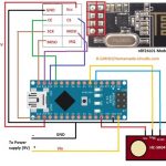
how can we implement this circuit to interface with arduino??
very cool. i'd like to make a NON-CONTACT humidity sensor that flashes an LED and run it off of a lithium coin cell. non-contact would mean little to no corrosion and mineral deposit from hard water, and a coin cell (1.2 to 3V) would let it run for a year or more. we've water to detect often enough in my basement where no-maintenance longevity is very useful.
one solution is to coat the metal on the PCB with conductive rubber/silicone. this would stop corrosion but not false readings because of mineral deposits from hard water. i was thinking of making some sort of home-brew capacitor where the liquid (water) would cause a small change in current flow that can jump-start the circuit so it becomes self-sustaining. if i'm not mistaken, your circuit uses little to no power when dry.
what do you think? any ideas? thanks!
My pleasure!
for a capacitor to be able to sense moisture it's plate would need to come in contact with the moisture, so that could also invite corrosion.
something has come in contact with moisture practically to sense its level according to me, so a non-contact operation looks improbable.
A "frosty glass" concept could be tried but that would work only under relatively higher moisture levels, not during lower levels
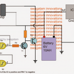
741 could consume as high 5mA when idle, much high for a button cell to sustain for long so a CMOS device looks to be a better alternative…we could opt for a mosfet or a NAND gate instead of the above shown circuit.
Sir can I use a dht humidity sensor in place of sensing mesh if yes then how to connect it.
Rishabh/Sonal, No it won't work with the above circuit because it's compatible only with a specially programmed MCU
Sir can I use a dht humidity sensor instead of sensing mesh,bcuse I have the one.If yes then how can I connect it.
So how should i keep the sensor to get the result? And how can i set the total device?
I have explained it in the article
Hallo sir, i knew that the sensor will be like this,, but the prob is, how can i make it at home,, its not available in market, i got one but that was too small, will that work? One more thing, i made the circuit and attached the sensor ports with two track of a barrow board, and when i touch touch it relay and led activates but situation do not change when i turn the pot,, it should change the sensitivity , isn't it? But sensitivity stays the same,, what happened here?
Hello Ria, there's no other way of making the sensor, it has to be in the shown form for getting optimal sensitivity.
The pot will not respond until some kind of resistance may it be in the form of humidity or finger touch is established across the sensor….as long as the sensor is open the resistance will be infinite and this would not allow you to see the pot control response at the output.
Sir,
can u please show me how can i make the sensor with picture?
riya, you'll have to etch it on PCB copper clad, please refer to the above comment response for Mr.green
Bro can u pls give me a micro controller based profesonal circuit design of humidity controller,, coz I need exact controlling of humidity for my bird incubator… will be great full brother…
Dear bro, it can be made by etching a copper clad such that the resultant PCB resembles the shown sensor in the diagram…the etched copper tracks must be very close to each other separated by not more than 1/2mm. design as many parallel tracks as possible to make the sensor more accurate and sensitive
Dear bro, i fond the problem, it is with my sensor,, if u dont mind can u pls show me how can i make this sensor by my own. Thanks
sorry bro i don't have a MCU design for this
by the way the above circuit will also give you a precise humidity control if the range is set correctly.
The professional DHT11 circuit is same as this, only with polymer coating above the comb E type structure, so polymer absorbs humidity in air and give reading output. try google Arduino humidity circuit, you will get desire results.
I myself on other hand want to make my own sensor so i plan to add satl or clay based coating on this circuit to get results.
good morning sir swagatam I'm interested in having a try this circuit but there is a part made me wonder. What is Sensing mesh and how i can get it? thanks
good day Rood,
sure, you may try the above design, the mesh is exactly as it's depicted in the diagram. The two intersected "E" type conductors could be etched over a 4 x 4 inch PCB very closely, the number of arms of the "E" could be increased for better sensitivity.
When humidity level increases, the tiny water droplets would tend to bridge the "E" gaps allowing a potential difference to develop across it, which would in turn be detected by the opamp, triggering the output stage
Hey brother, i need to tell you something , at first i made this circuit and worked as when i turn the potentiometer the led deemed and the relay turned off after sometimes,, but suddenly i think that the pin connection of the pot was wrong, and i rebuild it but now it turns on the led and relay when i power on the circuit but nothing happened when i spray water,,, but i didn't sprayed water at before, so was i correct before or now,,, please tell me… Thanks..
bro, the second attempt is showing wrong results, because when power is switched ON the relay should stay deactivated, and should activate only when enough moisture is present.
By touching the mesh with your finger would also provide equivalent results as during high moisture levels.
switch ON….touch the mesh firmly with your finger and adjust the preset until the relay just activates…that's it!….. your circuit is now all set.
Hi… I made this circuit and i used a water sprayer but it is not working ,,, and is the 10k variable pot's pin three is the negative point or pin 1 ? and is there any test point of this circuit to know that is it working or not ? Thanks ,,,
pin2 voltage must be lower than pin3 voltage for the output to change state from high to low and deactivate the relay.
in the presence of enough moisture the mesh will allow and leak just enough voltage for the transistor to conduct ad ground pin2 to ground making it lower than pin3, this will revert the output as discussed in the first line of this comment.
OK bro…
Dear bor,
i tried it but its not working.. when i connect with power the led turns on and nothing happens … wht could be the problem? is ther any test point in this circuit?? can u pls tell me more about the sensor? u know i searched a lot in internet to find a humidity controller most of them are so critical but urs on is so easy ,, dont take it other ways, is it that easy ? and to build a humidity controller i bought a expensive humidity sensor some times before that's model is "DHT11" can u pls check this sensor out and give me a humidity controller circuit with this sensor ? and by the way .. is there any way to have ur reply instantly or very early.? u know life is too short i dont want to wait for long where i can do more things meanwhile . Thank u 🙂
Dear bro,
The LED will keep glowing and the relay will stay activated as long as the humidity does not reach above the set threshold.
I think you should try the simple PCB track layout set up shown in the diagram as the sensor. If it does not work properly then we can go for the professional sensors.
I am sorry, this blog is the only medium through which we can communicate, due to lack of time other means won't be feasible for me….kindly bear with me.
hallow bro, i have a humidity sensor component, will it work in it ? or the touch switch will work with it. because humidity sensor is the correct component to sense the humidity as i guess, what do u say?.. .. 🙂
bro it depends how the sensor is designed to respond, if it produces a low resistance across it's terminals on sensing humidity then it could be used here.
Thanks A lot brother, I'll build it today, and let u know, and is there any name of the sensing mesh or any humidity sensor will work and and is the relay is 400 ohms? Thanks
All those who want more control or sensitivity, use darlingotn pair instead of single BC47 this way the circuit would be way MORE sensitive.
you are welcome Bro, the mesh is a simple PCB copper track layout spaced at about 2mm between the tracks.