In this article I have explained a simple water saving irrigation system circuit idea which can be used for implementing an efficient water management and control in farms and irrigation systems.
The idea was requested by Mr. Ajinkya Sonwane, Mr. Akshay Kokane and Mr. Kunal Raut, studying in AISSMS IOIT College of Engineering.
Circuit Objective
As per the request, water needs to be controlled and managed at a given predetermined rate depending on the type of crop and its necessity.
The easiest possible solution to this could be in the form of solenoid timers which could be programmed once by the farmers for enabling an automatic water management, everyday, without any further intervention, until the crop or season changes. The timer is supposed to be extremely flexible, easy to operate and cost effective.
The idea here is to connect DC solenoids valves at different nodes of the distribution pipe network and control these solenoid valves using timers.
The timer controller unit could be positioned in a specific position (control room) for enabling the farmers to set the timing as per the needs anytime, as required, and the signals could be appropriately transmitted to the relevant valves through wires for executing the controlled release of water across the given area.
The following circuit idea using the IC 4060 may be considered perfectly suitable for the proposed precision water management in irrigation system.
The circuit functioning can be understood with the help of the following points:
Circuit Diagram and Description
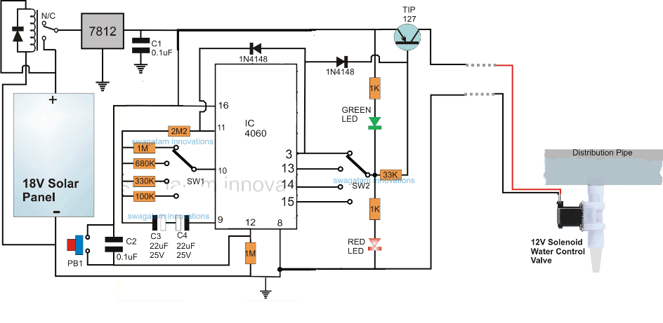
The IC 4060 can be seen configured in its standard timer/oscillator mode.
Pin#10 and pin#9 are associated with the time delay setting for the output pinouts 3, 13, 14 and 15.
The SW1 switch facilitates the time delay selection through the respective resistors which decides for how long the output of the IC may be rendered active, ensuring that the connected solenoid valve stays switched ON and in a water supplying mode only during this period of time.
The indicated timing resistors for SW1 are arbitrarily arranged and must be appropriately calculated during the actual implementation as per the crop specifications, and water availability.
SW1 is specified for a 4 position selection which can be increased to more positions by simply using a switch with more number of contacts and by adding subsequent number of resistors in the appropriate order.
SW2 is also a rotary switch identical to SW1 and is positioned for selecting the switching mode of the solenoid valve.
Pin#3 provides a continuous ON mode for the valve for the selected time slot after which the valve is switched off until the next day, whereas pin13, 14, 15 provides an oscillating (ON/OFF/ON/OFF) activation mode for the solenoid so that the water is managed in a more controlled manner, however this may be optional if the valve nozzle is correctly dimensioned for a restricted flow as per the given criteria.
Delay Time Setting
It can be done by appropriately calculating the pin#10 and pin#9 R and C values as per the following formulas:
f(osc) = 1 / 2.3 x Rt x Ct
2.3 being a constant will not change.
It is important to maintain the following shown criteria correctly in order ensure proper functioning of the output delays.
Rt << R2 and R2 x C2 << Rt x Ct.
Rt corresponds to resistors at pin#10, R2 is for the resistor at pin#11. C2 indicates the capacitor at pin#9
Powering with Solar Panel
The whole system can be seen powered through a small solar panel which makes the entire system full automatic.
When dawn sets in, the solar panel voltage gradually rises and at a particular point reaches a 12V level activating the connected relay.
The relay contacts instantly connect the solar voltage with the circuit initializing the procedure wherein the IC pin#12 is reset by C2 forcing the IC to begin counting from zero.
All the outputs are rendered with a zero logic initially which makes sure that the TIP127 transistor commences with a switch ON condition and triggers the connected solenoid valve.
If SW2 is positioned with pin#3, the TIP127 and the valve stay switched ON continuously supplying water through the nozzle in a dripping manner until the set timing is elapsed and pin#3 becomes high.
As soon as pin#3 goes high the logic high instantly latches pin#11 of the IC and stops the IC from any further counting, freezing the procedure permanently for the day. The logic high is also transferred to the base of the TIP127 switching it OFF along with the valve system. The water supply to the crops at this moment gets halted.
How to Reset the System
At dusk when the sunlight weakens and gets below the relay holding level, the relay is switched OFF which also switches OFF the associated circuit stages, until the next day when the procedure undergoes the triggering of a fresh cycle.
PB1 is used for resetting the proceedings at anytime for enabling a new start for the circuit.
Many number of the above explained systems can be implemented at the specified nodes of the distribution pipe for achieving the desired precision water management in irrigation systems.
How to Calculate the Timing Resistors for the water saving irrigation system
The timing resistors associated with SW1 can be calculated with some experimentation as given below:
Any arbitrarily selected resistor may be initially switched with SW1, say for example we choose the 100k resistor as the reference.
Now switch ON the circuit to initiate the procedures, the red LED will be seen coming ON.
As soon as the circuit initiates monitor the timing using a stop watch or a clock and watch when the green LED turns ON switching OFF the red LED.
Note the timing achieved using the particular resistor which is 100K in this case.
Let's say it resulted in a delay period of 450 seconds, then taking this as the yardstick other values could be simply determined through a simple cross multiplication as given below:
100/R = 450/t
where R stands for the other unknown resistor value and "t" is the desired time delay for the solenoid valve.
If you have more suggestions regarding this water saving irrigation circuit using timers, please feel free to express them through the comments.


Questions & Answers
hi sir
can you give a recommendation or examples of what rotary switches to us in this circuit?
thanks
gee
would a dip switch work?
Yes, a dip switch can be also configured.
Hi gee, the switches can be 4-way, single pole switches
Hi, Does a 12v solenoid valve require a driver like relay or can I connect directly to a 12v power supply with a flyback diode and switch?
Hi, the relay may be required for switching the solenoid ON/OFf in response to an external signal. But normally, you can connect the solenoid directly to an appropriately matching supply source.
Sir,
I want to know, is there any necessity of flyback diode to 12v solenoid valve??
Hi Nitin, yes it will require a flyback diode, it’s not shown in the diagram by mistake.
Thanks for quick response sir.
Sir, I don’t know how to choose diode, so plz suggest me which diode should used for 12v solenoid valve??
Hi Nitin, a 1N4007 diode will be enough, you can use it. Connect the cathode with the positive of the solenoid, and anode wit the negative of the solenoid.
Hi, thanks for the quick response. The capacitor has to be tatalio? And what are the values so that it works cyclically every 30 days. Many already.
Hi, the capacitor should be non-polar by nature therefore a tantalum might not be a good option because these are mostly polarized. If you can get a non-polar tantalum then definitely you can use it.
For the calculations you may have do it with some trial and error. Initially you can try 0.047uF at pin#9, and 10K at pin#10, and carefully check how many seconds delay is generated at pin#3 of the IC. Once you get this example value you can evaluate the actual required value for the R/C through cross multiplication.
The delay at pin#3 of 4060 will be increased 10 times more by the IC 4017, so it you set 3 hours at pin#3 of the 4060, this will converted to 3 x 10 = 30 hours by the IC 4017.
Hello I would like a cyclic timer circuit every 30 days .. I have to turn on 2 water pumps alternately every 30 days. From already thank you very much. Greetings from Buenos Aires, Argentina
Hello Carlos, you can try the following design:
https://www.homemade-circuits.com/how-to-make-long-duration-timer-circuit/
make sure to remove the diodes across pin#11 to pin#11 of the two ICs to get cyclic action, and also make sure to use a metallized high quality cap for C1
dear sir, how i can make running led board for advertisement?
you can try the following concept
https://www.homemade-circuits.com/2016/09/welcome-chasing-led-display-circuit.html
hello:)