SMPS is the acronym of the word Switch Mode Power Supply. The name clearly suggests that the concept has something or entirely to do with pulses or switching of the employed devices. I have explained how SMPS adapters work for converting mains voltage to a lower DC voltage.
Advantage of SMPS Topology
In SMPS adapters the idea is to switch the mains input voltage into the primary winding of a transformer so that a lower value DC voltage may be obtained at the secondary winding of the transformer.
However the question is, the same can be done with an ordinary transformer, so what is the need of such complicated configuration when the functioning can be simply implemented though ordinary transformers?
Well, the concept was developed precisely for eliminating the use of heavy and bulky transformers with much efficient versions of SMPS power supply circuits.
Though the principle of operation is quite the similar, the results are hugely different.
Our mains voltage is also a pulsating voltage or an AC which is normally fed into the ordinary transformer for the required conversions, but we cannot make the transformer smaller in size even with current as low as 500 mA.
The reason behind this is the very low frequency involved with our AC mains inputs.
At 50 Hz or 60 Hz, the value is tremendously low for implementing them into high DC currents outputs using smaller transformers.
This is because as the frequency decrease, the eddy current losses with the transformer magnetization increases, which results in huge lose of current through heat and subsequently the whole process becomes very inefficient.
To compensate the above loss, relatively larger transformer cores are involved with relevant degree of wire thickness, making the entire unit heavy and cumbersome.
A switch mode power supply circuit tackles this issue very cleverly.
If lower frequency increases eddy current losses, means an increase in the frequency would do just the opposite.
Meaning if the frequency is increased, the transformer could be made much smaller yet would provide higher current at their outputs.
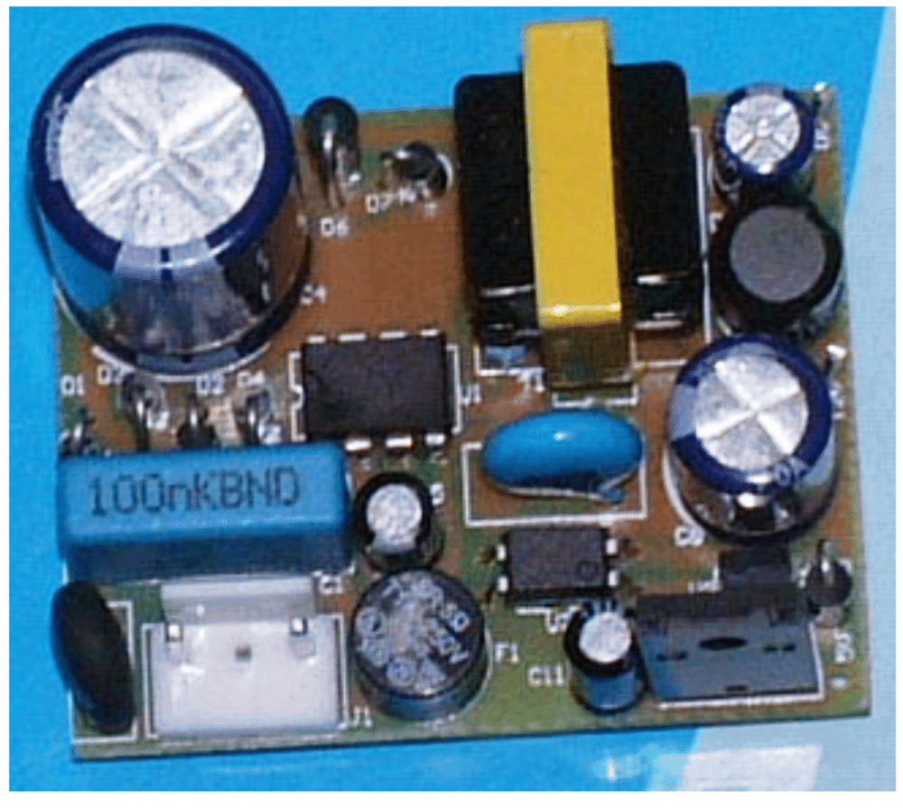
That's exactly what we do with an SMPS circuit. So I have explained the functioning with the following points:
How SMPS adapters work
In a switch mode power supply circuit diagram, the input AC is first rectified and filtered to produce relevant magnitude of DC.
The above DC is applied to an oscillator configuration comprising a high voltage transistor or a mosfet, rigged to a well dimensioned small ferrite transformer primary winding.
The circuit becomes a self oscillating type of configuration which starts oscillating at some predetermined frequency set by other passive components like capacitors and resistors.
The frequency is usually above 50 Khz.
This frequency induces an equivalent voltage and current at the secondary winding of the transformer, determined by the number of turns and the SWG of the wire.
Due the involvement of high frequencies, eddy current losses become negligibly small and high current DC output becomes derivable through smaller ferrite cored transformers and relatively thinner wire winding.
However the secondary voltage will also be at the primary frequency, therefore it is once again rectified and filtered using a fast recovery diode and a high value capacitor.
The result at the output is a perfectly filtered low DC, which can be used effectively for operating any electronic circuit.
In modern versions of SMPS, hi-end ICs are employed instead of transistors at the input.
The ICs are equipped with a built in high voltage mosfet for sustaining high frequency oscillations and many other protection features.
What Built-in Protections do SMPS Have
These ICs have adequate built in protection circuitry like avalanche protection, over heat protection and output over voltage protection and also a burst mode feature.
Avalanche protection ensures that the IC does not get damaged during power switch ON current in rush.
The over heat protection ensures that the IC is automatically shuts off if the transformer is not wound correctly and draws more current from the IC making it dangerously hot.
The burst mode is an interesting feature included with the modern SMPS units.
Here, the output DC is fed back to a sensing input of the IC. If due to some reason, normally due to wrong secondary winding or selection of resistors the output voltage rises above a certain predetermined value, the IC shuts off the input switching and skips the switching into intermittent bursts.
This helps to control the voltage at the output and also the current at the output.
The feature also ensures that if the the output voltage is adjusted to some high point and the output is not loaded, the IC switches to burst mode making sure that the unit is operated intermittently until the output gets adequately loaded, this saves power of the unit when in standby conditions or when the output is not operative.
The feedback from the output section to the IC is implemented via an opto-coupler so that the output remains well aloof from the input high voltage mains AC, avoiding dangerous shocks.



Questions & Answers
Dear sir, how do I use this formula to calculate link capacitor?
Cin= 2×Pin ×(0.25+1/pi ×ArcSin(Vbulk(min)/√² ×Vin(min))) / (2×Vin(min)² – Vbulk(min)²)× fline(min)
Where:
VIN Input Voltage 85 –115/230 — 265 VRMS
fLINE Line Frequency 47 –50/60 — 63 Hz
VOUT Output Voltage IOUT(min) ≤ IOUT ≤ IOUT(max) 11.75 — 12 –12.25 V
VRIPPLE Output Ripple Voltage IOUT(min) ≤ IOUT ≤ IOUT(max) 100 mVpp
IOUT Output Current 0 — 4 A
η Efficiency 85%
What I am trying is below:
First, the denominator:
2×Vin(min)² – Vbulk(min)² × fline(min)
(2 × 85² – 75² ) × 47
= 414775
And Second, the numerator:
2 × Pin ×(0.25+ 1/pi × ArcSin(Vbulk(min)/√2 ×Vin(min)))
2 × Pin ×(0.25+ 1/pi × ArcSin(75/ √2×85))
2 × Pin ×(0.25+ 1/pi × ArcSin(75/ 120.208))
2 × Pin ×(0.25+ 1/pi × ArcSin(0.6239))
2 ×Pin ×(0.25+ 1/pi × 38.6029)
2 ×Pin ×(12.5377)
But the resulr is too huge for Power in watt:
126uF = 2× Pin × 12.5377 / 414775
My questions:
1. Is the denominator correct?
2. Is the numerator correct?
3. Why wattage is so hight if the above calculation are all correct
Thank you sir
Kamus
I am sorry Kamus, it might take a lot of time to investigate your calculations, and due to lack of time it may be difficult for me to figure it out.
I can only help with general circuit ideas.
Ok sir Np. Thank you for your reply anyway.
how i make customized power supply that powering a juicer machine at variable voltages like 200V,250V,AND 400V.
You will need a variac for that, because SMPS will supply DC not AC
What kind of variac?
Please Google it, you will get the explanation with images.
Hello!Atx power supplies have a switch for 110v-220v selection.How does this switch work?
Atx power supply has two large filter capacitors in the input section. Usually 470 microfarad is 200V.Why is the capacitor not one?
470 microfarad 200V equivalent to two capacitors 1000 microfarad 400V one can not be used?
The switch must be used depending on the input voltage specification. For 220V inputs, slide it towards the 220V side and for 120V supply sockets slide it on the 120V side. I have not checked the capacitor and connection details, so I cannot advise on that
Hi Swagatam,
Thank for your efforts.
I am Looking for 2500W/50A Power supply. Pls. help.
Uday
Thank You Very Much.
Cirtainly i will try this.
You are most welcome!!
Hi Uday, I think you can try the following concept and modify it suitably as per the intended specs
https://www.homemade-circuits.com/2014/06/smps-2-x-50v-350w-circuit-for-audio.html
plz post 24v 500ma smps circuit diagram
Hey sir Swagatam, how can I go about designing a high frequency (20 kHz or more) switched mode DC power supply.
Hi Nomsa, you can do it through a simple IC555 based flyback switch mode circuit
Hi Swagatam,If you could help me by sending the circuit of +ve & -ve 38 volt 10 amp SMPS Circuit for my mosfet amplifier.please mention the specifications of transformer also.
Hi Shaji, you can modify the following concept as per your specific requirement
https://www.homemade-circuits.com/2014/06/smps-2-x-50v-350w-circuit-for-audio.html
H!I need a the schematics for a TV: lg 50pc55 that's smps board: EAY32957901.
If someone have one or a link, please let me know.
Thanks!
Hi, I'll try to find it, if I get one will update it in this site…
Hi Swagatam da,
Thanks a lot for such a simple yet comprehensive Idea. I am very much confident now to go for my first self-made PSU. Just one thing, can you please suggest me a place where I can order the Ferite E Core Transformer, because till now I used to go to Radio Equipments Co. @ Chandni Chowk (Kolkata) for my electronic needs, but it seems they are not able to provide customized transformers as in this case.
Is it recommended to self-wind the coils at home with prescribed gauzed wires?
Thank you Rajarshi, I am glad I could help….
…. yes, the transformer cannot be procured ready made from anywhere, only the transformer spares needs to be procured and then assembled at home by following the given winding data
Could you help me to make 12 volt smps for l e d light 18 watt
presently I do not have this circuit, will try to publish if possible.
Is it safe to remove c7 if I want to connect the ground on the dc side to mains ac ?
…you can try the following circuit if isolation is not a concern for your need:
https://www.homemade-circuits.com/2014/02/simple-1-watt-to-12-watt-smps-led.html
Hi,
I see that most smps mobile chargers have a 2.2nf or so capacitor connecting the dc ground on primary and the dc ground on the secondary side. I couldn't understand the use of this capacitor. Why is this cap(c7) needed ?
I want to measure the primary ac voltage without isolation and hence want to connect the ground of the dc to the ground on the primary side. Is it safe to do this ?
Thanks
Krishna
Dear Krishnakumar,
you can take the help of the following article for further info:
https://www.homemade-circuits.com/2015/10/calculating-inductor-value-in-smps.html
Dear Swagatham,
Thanks for your quick response. I have been opening up mobile chargers from ranging 60/- to 500/- and observed that all of them have this capacitor. The cheap ones use self oscillatory circuit based on Transistor and the expensive ones use IGBT based drives with forced oscillations. I will try out my instrumentation circuit by removing this capacitor and keep you updated.
For the next phase I am planning for a transformer less power supply followed by a cheap 5v regulator like http://www.ebay.in/itm/DC-DC-3A-Buck-Converter-Step-Down-Module-Power-Supply-DIY-4-5-28V-to-0-8-20V- /131634145521?hash=item1ea601a8f1:g:D~gAAOSwA4dWJ1LQ
I plan to use a zener to clip the input voltage to ~ 15v @ ~200mA. The 5v regulated output should be able to reach upto 500ma. Let me know yout thoughts on such a circuit.
Thanks
Krishna
Dear Krishnakumar,
C7 is not required according to me….I can't figure out the exact intention behind introducing this capacitor, because it might affect the 100% isolation criterion of the SMPS
Dear Swagatam,
Assuming that there is going to be no human contact on the dc side, is it safe to remove c7 in this circuit OR replace c7 with a short.
With c7 in place, is this an example of a 100% isolated dc smps power supply ?
Thanks
Krishna
Hi, if the capacitors are referenced to ground then most probably these are for filtering high frequency content or noise in the circuit.
It's absolutely not safe to use the primary side of any SMPS for a DC application…
hello sir, which device can be used as a replacement of transformer in regulated power supply
In SMPS the ferrite transformer cannot be replaced, it's the heart of the system.
hello sir,which device can replace transformer in regulated power supply???
Can you please tell me if a UPS WITH 12 volts 1 amp OUTPUT. Is available.I require this for the modem .since the modem takes a few minutes for configuration each time the current goes off
you may try the circuits explained here:
https://www.homemade-circuits.com/2013/03/simple-dc-ups-circuit-for-modemrouter.html
sir how to do an smps wich is controlling by mosfet as a switch pls reply simbu389@gmail.com
you can try the following circuit:
https://www.homemade-circuits.com/2014/03/12v-5-amp-transformerless-battery.html
Hey please send me the circuit for 5v DC 1Amp from 230v AC. kmhatre14@gmail.com
you can refer to the following article:
https://www.homemade-circuits.com/2014/02/220v-smps-cell-phone-charger-circuit.html
Thank you very for the valuable tutorial. Can I get some ideas for designing various voltage and current rated switched mode power supplies? Are there any easy understanding steps ? What should be modified in the design to change the o/p to 5V-2A of ratings. Please let me understand the way for choosing the transformer for different ratings of o/p. Thank you 🙂
Thanks Lomas, an SMPS will continue to produce a constant voltage at the output as per its rating, regardless of the input mains input (within 100V and 285V)
Thanks Swagatam. What happens when input ac voltage varies ? For example can it be capable to provide the rated output when AC voltage varies from 110V to 220V ?
the primary side of an SMPS is a complex section and cannot be modified or tweaked easily, and is not recommended.
the transformer secondary can be adjusted some for getting a desired selected output.
You may refer to the article for more info:
https://www.homemade-circuits.com/2015/07/turns-and-voltage-ratios-total-voltage.html
https://www.homemade-circuits.com/2015/04/how-to-make-variable-smps-driver-circuit.html
https://www.homemade-circuits.com/2015/04/how-to-make-variable-current-smps.html
yes that's correct, PWMs or the duty cycle can be used for adjusting current, not voltage.
how much amps is possible in viper22a sir
1 amp max.
Can you please share 48 volt SMPS circuit.
you can built the following circuit:
https://www.homemade-circuits.com/2012/03/how-to-make-simple-12-v-1-amp-switch.html
double the number of turns in the secondary and adjust R6 until 48V is achieved at the output