In this post I have explained a simple transformerless SMD 5630 type LED tube light circuit which can be built by anybody for illuminating home interior cheaply. The idea was requested by Mr. Smeet.
Technical Specifications
I am a very big fan of your website and it has been much helpful to me in my college projects i wanted to design a driver to drive 1 to 50 SMD 5630 LE and input voltage 110 to 235 v , forward voltage of LED is 3.3v and i need a very efficient circuit i.e all LED should be maximum brigh would u please help us with this circuitlooking forward to your reply soon
thank you
The Design
The LED model shown below is the 5630 type surface mount LED from Samsung which has the following typical voltage and current specifications:
Forward voltage: 3.3V
Optimal Current: Between 50 and 150mA
Power dissipation: 0.5 watts approximate.
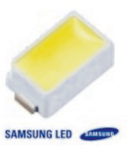
Although it is recommended to operate any LED via a current controlled SMPS, for simplicity sake the following compact transformerless power supply may be tried and could prove as good as it's other counterparts.
The present design is based on my previous variable transformerless power supply design, which enjoys a novel crowbar network concept for safeguarding the involved sophisticated devices.
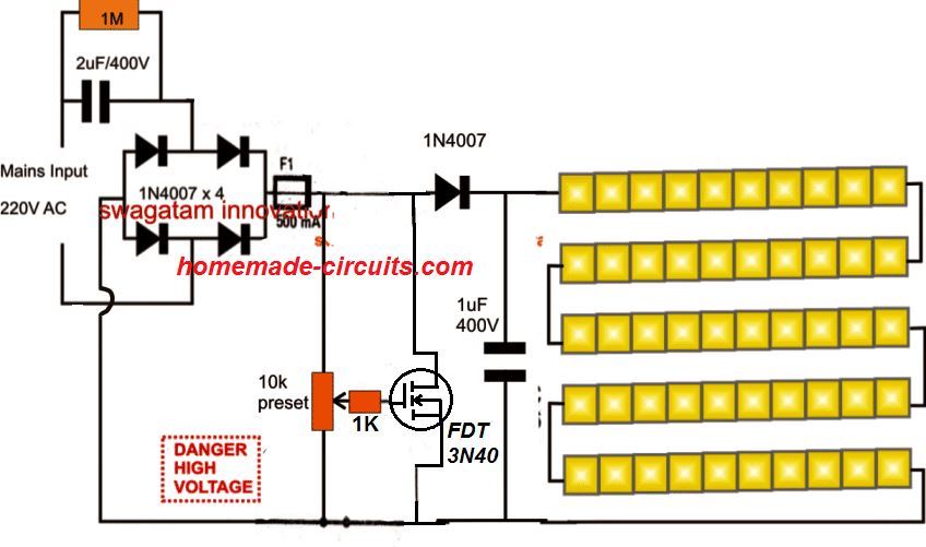
The proposed 5630 SMD LED driver or compact tube light circuit may be understood with the help of the following discussion:
Circuit Operation
The input capacitor which is a high voltage metalized polyester 2uF/400V rated capacitor drops the mains 220v to desirable limits and feeds the connected the bridge rectifier stage.
The bridge rectifier in conjunction with the 1uF/400V rectifies the AC into a 330V DC.
This high DC is applied across the crowbar network comprising the zener, MOSFET and the preset in the stage.
The preset is appropriately set such that the the output matches the total forward drop of the connected LEDs.
If 50 LEDs are connected in series at the output the above preset must be selected to produce precisely a voltage of around 50 x 3.3 = 165V
Once set, this voltage gets clamped and never exceeds even under worse conditions.
The LEDs thus stay safeguarded from all possible high voltage and surge current hazards.
This happens owing to the fact that the mosfet tends to conduct and ground the output voltage whenever the voltage across its drain/source tries to rise above the set value which may be 165V as assumed here.
Other different number of LEDs may be opted for at the output as per individual preferences, and the preset set up as per the calculations discussed above.
In the shown circuit diagram all the LEDs are connected in series to form a chain of 50 LEDs connected one behind the other with anode of one LED connected to the cathode of the other, and so on.
NOTE: Please connect a 50 Ohm / 1 watt resistor in series with the LED chain for better safety of the LEDs
Circuit Diagram
THE WHOLE CIRCUIT WOULD BE FLOATING WITH LETHAL MAINS AC, EXTREME CAUTION IS EXPECTED FROM THE USER WHILE TESTING THE CIRCUIT IN AN UNCOVERED POSITION.
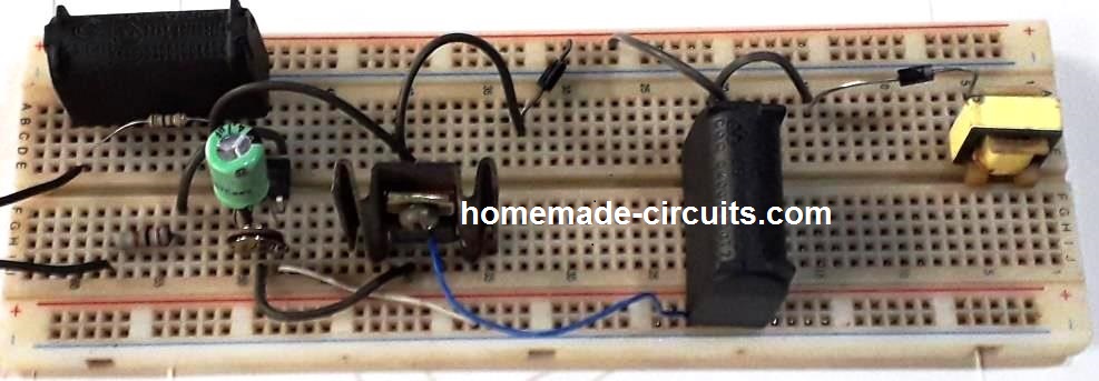
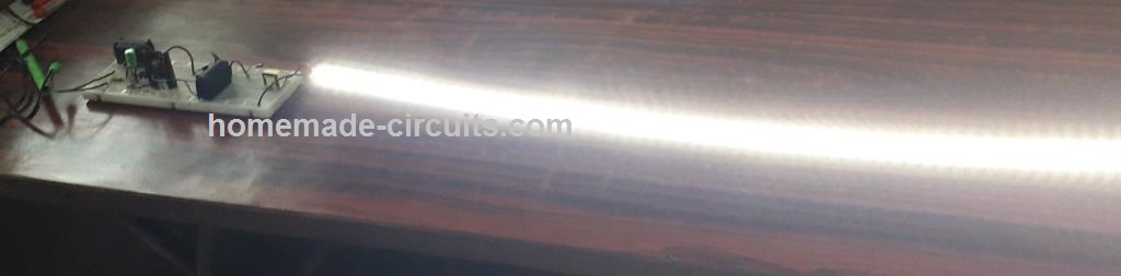
Feedback from one of the dedicated readers of this blog, Mr. Raghavendra Kolkar:
Hello sir good evening, thanks a lot for sending the circuit diagram of led driver. After 5 failures finally the circuit was successful.
I am sending you the picture of the driver and working.
Thanks a lot, so far all your circuits are working well and nice.




Questions & Answers
Hello sir,
I think zeener should be removed to drive 50 led to get 165v out put
Helo Avijeet,
You are correct the zener does not have any relevance here.
Another issue could be the heating up of the preset and the resistor….the values should be either carefully selected or the gate of the SCR should be attached with the separate capacitive power supply stage. I'll try to update it here soon.
Is above mentioned issue also persists if we use the above circuit in low voltage output as it is in schematics(say 12v or 24v)for less no of led's
for lower voltage requirements, it would be better to include the zener as it would keep the output within the zener voltage under all conditions.
Hello Shail,
Yes you can use the above circuit for types of low current LED driver application.
According to me nothing would overheat in the above discussed circuits.
yes…
you can use them, but the illumination may not be optimal.
hi sir can i connect 20nos of 1w power led with this circuit and what is max output current of this circuit
thanks
hi Vaibhav,
yes you can use them, connect them in series, max current is not known to me because i haven't checked it practically.
thankk u sir and b lated happy vijayadashmi
Thanks very much Vaibhav.
hi sir for the above circuit. i am going to connect 10 5630 leds in series can i able to get 150mA of current constantley to the leds so that my leds will give maximum light.
Hi Unknown,
No with 10 leds the current would also drop with votage, so according to me you will have to use a least 50 to 60 leds for acquiring or sustaining 100mA current with any capacitive transformerless circuit
Dear Sir,
I have built the 2nd circuit with the separate low value capacitor stage for the gate trigger as in the drawing but im not getting any voltage in the 100uf 50v capacitor. DMM shows only 0.5 volts
Dear Thejus,
The circuit diagram needs a little fixing, I'll do it soon, in the meantime you can try the following design:
https://www.homemade-circuits.com/2012/08/high-current-transformerless-power.html
Dear Sir,
Can you suggest any transformerless power supply to run 50 or 60 led in series.
I have some 5mm white leds laying with me. the forward voltage of the led is 3.7v and current arround 30ma
Dear Thejus,
You can try this design:
https://www.homemade-circuits.com/2012/04/how-to-make-led-bulb-circuit.html
if to take only half of that is 30 leds, what would be the modification of circuit ??? I hope your answer thanks
no modifications would be required, any desired led quantity would work here.
Hi sir,
I 'm going to make your circuit, I have 50 pcs of LED SMD white 0.5 watt and 150ma. can i use your circuit? what is the triac number?
Hi Mohammed,
yes you can use the above circuit, the triac number is BT136 but an easier alternative is given in the following article which you can also try:
https://www.homemade-circuits.com/2012/04/how-to-make-led-bulb-circuit.html
Hi sir. I made this circuit.when i switch on leds are blinking very fast.why like this? Can i remove triac?
Hi Mohammed, you can remove the triac and connect a 100 ohm relay coil in series with the LEDs, this will protect the LEDs from sudden voltage surge….or alternatively keep the triac as given and increase the 1uF/400V to 50uF/400V for getting rid of the fluctuations.
hi guys. I was busy with research into the smd 5630 led when I stumbled on this post. I looked at the drawing and there is some short falls to it. I also use long strings(81 leds) connected to mains power230v ac rectified to dc . what we found with lots of research is that you can not use any light string with out a current controller. let me explain. when leds start to heat up then the voltage drop over the led decreases, this cause a increase in current which again cause more heat. at the end you will have a dead circuit. we use a basic circuit, sorry I don't know hoe to upload a picture . upload.wikimedia.org/wikipedia/commons/thumb/f/f7/Const_cur_src_111.svg/220px-Const_cur_src_111.svg.png . en.wikipedia.org/wiki/Current_source
we use MJE340 for the transistor, dz1= 2.7v 1watt,R1=100K 1Watt. R2 needs to be calculated. easy way is r=v/I v is 2v I is the current of your led. for example I need 60ma through my string then R2= 2/0.06 =33ohm. note do not try to use your led at maximum data sheet power because they always produce too much heat rather go for 60% rated current.
Thanks! you are right, the fact pretty known though, and I am sure most of the hobbyists already know about this.
I have covered comprehensively about this cricatility and many more in my other relevant posts, with calculations.
The above article design was meant for tackling four fundamental things:
the circuit needed to be cheap, transformerless, surge protected, and easy to assemble.
The heat factor could be rather solved by using an aluminum base PCB or the LEDs could be itself mounted over an aluminum plate.
The above circuit attempts to include all these features in one and therefore the current control was ignored.
However the above the design is already too inefficient as far as amp spec is concerned.
The triac would dump a lot many amps and I am afraid we would have rather an under illuminated LED string.
Furthermore the triac network woulds also make sure that the voltage across the array stays close to the rated voltage spec of the LEDs.
Together, the above circuit is pretty much within the safe boundaries of the devices used and could be considered safe.
sorry I forgot to mention. the board is live and when you design a board you should make sure that you have enough clearance between any led or copper the earth or mounting holes of your enclosure. at least 3mm.
Hi Sir,
Nice to meet you after a long…my new request is on driving 5630 led at120mA which is rated at 150mA max with 12v 5-8amps dc power supply…..for example 5630 led strip module( 3 led in series with a resistor).
Hi Vinu, you will need to assemble three LEDs in series with a 17 ohms 2 watt resistor, you can add more such assemblies in parallel for getting as many LED strings as you want.
if suppose i want the above setup which i asked you as a query to use it in car dc supply what should i do to get the 5630 led at its full brightness without over heating the leds…..(making a DIY led strip using 5630 led)
sir kindly tell me the nearest value resistor and setup with its max output….which can easily sourceable from electronic shops….
Vinu, for 120mA use any value near 17 ohms (2 watt) for each 3 LED string.
…it should not be less than 17 ohms.
Sir,
1.Should i use LM317 Voltage regulator for 5630 leds powering from automobile 12v dc….???
2. Give me a LM317 regulator setup diagram for this 5630 leds and also for high power 1 watt*3 leds in series…
Vinu, you can use the first circuit from the following link:
https://www.homemade-circuits.com/2013/06/universal-high-watt-led-current-limiter.html
Calculate R1 as per the given formula.
Sir,
1.Should i use LM317 or LM338 for 5630 leds and also for 1watt leds….
2.Is there any possibilities without using current regulator for this leds….
Vinu, Use LM338 if the total current requirement is beyond 2 amps,
if a sufficiently large heatsink is employed then the current regulator stage can be eliminated, furthermore a fan cooling could be employed for better safety of the LEDs
hi sir
i tried the setup what u mentioned me…it works but the resistor is getting hot…can i connect the entire series arranged leds connected in parallel with one 17ohm 2watt resistor..??? if so when i use such setup what will happen…???
can i drive 5630 led above 120mA which has Max.150mA. if so let me know the resistor value for using in car parking plug…power supply 12-14v 3.5-5amps….or more
want to run those 5630 leds at its full output at 150mA max will it be possible and if so let me know the resistor value.
use 3 in series with a 27 ohm 1 watt resistor
I have calculated the above for 14V input max… for better safety…
for 12V, the resistor should be 14 ohms/ 1 watt or 2 watt
earlier there was a thyristor instead of a triac which I later replaced with a triac, the markings are for the SCR which was previously present in that position….
Hi…Swagatham Ji,
Please give me the name of transformerless led driver IC ( like MBI6001 ). I want to run 2,3,4 watt led lamps.
Nikhil V G
nikhilkbd@gmail.com
Hi Nikhil,
there's no specific name for this IC, and it's not rated for high watt operations, only 20mA LEDs can be used with it
I'll try to update the article soon in my blog. thanks!
Hi sr, firts of all, sorry for my bad english u.u.
Second, i have 8 lamps with 14 leds 5630, it means that i have to use 46.2 volts, how i can drop the voltage to that? because in your diagram its 165 volts
Hi carlos, you may simply remove the triac and the resistors and connect a 50V 1watt zener right across the output capacitor…this will hold the voltage to around 50V….
thanks, another question, the capacitors are electrolitic or ceramic?
I make it, and before the zener give me 330v, after the zener only 7 volts, any idea? im using 1N4756A
capacitors are polypropelene PPC type, check your zener diode it might be rated at 7V, or may be faulty…
hi,
i use a circuit for run30 5630 smd in series .but after two or three month one smd short and when replace it and run again another smd short. ad this is going on.we use 205n400 capacitor .
remove the triac and the preset…and simply add two or three 1 watt zener diodes rated at 30 x 3.3 = 99V or 100V..that is 100V/1 watt zeners, 2 nos
add this parallel to the capacitor 1uF/400V filter cap
….and make sure the LEDs are not getting hot…if they are then use a heatsink for the series.
Hi Swagatam,
Hope you are doing good!
May I request you to design a high output LED circuit with 12 Bright White LED's. Similar to the DRL's used in the cars. Should be 2 sets of 6 LED's, that can throw some high bright light.
Thank you,
Manjunatha
Hi Manjunath,
for a 12/13V supply 6 LEDs cannot be used….you can put three in series and add more such strings in parallel….you can refer to the second circuit concept from the following article:
https://www.homemade-circuits.com/2013/06/universal-high-watt-led-current-limiter.html
Hello swagatam,
I want to drive 90 5630/5730 leds using this circuit.
(I wanna drive each at these specifics Vf=3.3-3.4; If=130-150mA)
Considering forward voltage drop of 3.4v per led the total would be 3.4×90=306v.
Without the dropping capacitor c1, the direct rectified dc voltage for 220-260vac would be between 310-370vdc.
So safe consideration would be say 350vdc.
With 350Vdc as Vs and voltage drop of 306v(with If=140mA) for the leds a 300ohm resistor could be used for the led string.
Now i wanna know if the above circuit will work with these specs and what changes would be required to be made to your circuit ?
Also where do I shunt a mov for surge protection ?
Looking forward to your reply, would really appreciate it.
Hello Jeremiah, without C1 your LEDs will not last long…so C1 is a must.
for getting 150mA you may have to use a 4uF/400V capacitor for C1
for yout application you can ignore the triac circuit it wn't be required….instead use an 10 ohm NTC in series with the input capacitor for arresting the initial surge currents.
Hey,thnx fr the reply…
Btw, Will the circuit give out the needed 306Vdc
Also does using much higher rated capacitor(1.2kv) change the output ?
I'm unable to find a 10ohm.ntc, can I use an mov?
yes the discussed circuit will be able to provide the required amount of voltage which will equal to the input supply limit….1kV indicates the breakdown limit of the cap, the output can be never above the input supply level
NTC is better suited than MOV for this application, you can try a 5 ohm NTC
Will 10k BTC work??
Also,, can I use two 5ohm ntc in series?
you can put two in series but a single 5 ohm will also do!
Thnx fr the reply… Will test test it out and revert…
Hello sir,
I am Tanuj, from KOLKATA. Can you please tell me how many 5730 smd led is connected in parallel or series with transformerless power supply? The power supply made by 1uf/400 volt capacitor with paraller connected 1M resistor.after that adding bridge rectifier and zener diode.
Hello Tanuj, it will depend on the output voltage setting of the power supply…..divide the output voltage with 3.3V, that will give you the number of LEDs that could be accommodated.
I am operating 1w 3LEDs by Nokia Mobile standard battery. When I connected to the LEDs about 1 yard far, the brightness is optimum but about 12 yards far the brightness is not optimum.so I am guessing brightness is decreasing with distance. How can solve that issue???
you mean to say when LED wire length from the battery is increased, brightness goes down?? then make sure the battery is close to the LEDs
Yes u got my problem but the LEDs need to keep 12 yards distance from battery with circuit for lighting the outer space. Please suggest me alternative way. If I connect capacitor 10v 1000uf in LEDs positive and negative then that situation will improve??
There's no solution to this except keeping the battery near to the LEd, because as the wire length increases the resistance offered by the wire also increases causing a proportionate amount of decrease in the current for the LED….
If I increase positive's wire gauge or both then it can develop the situation??
I don't think that will do any good….the distance which the electrons have to cover is causing the issue
Hi
What should i do to powering 200 5630 leds with this circuit? I think that i must change resistor of triac… right?
Hi, actually for long LED strings a triac controlled output is simply not required. The surge can be controlled using a resistor, a NTC or an MOV. You can configure it as explained in the following articles:
https://www.homemade-circuits.com/simplest-100-watt-led-bulb-circuit/
Assuming you have 220V as the input, You can make two strings having 100 LEDs each with a calculated limiting resistor, and aditional protection such as an NTC or MOV:
I want triac spification for led tube light driver or triac model number.
you can try BT136
I have 165 SMD led connected in parallel and every 5 in series so I need a voltage drive with 400 volt Dc output and my input is 220 V AC. How I can change the above circuit to fit my case thanks.
You can use the first circuit from the following article:
https://www.homemade-circuits.com/how-to-make-led-bulb-circuit/
you will have to first adjust the output voltage to match the FWD voltage of the 5 SMD LEDs in series.
My SMD Led forward voltage is 12 Volt and I have a group of 5 leds in parallel connected in series with another 5 Leds till 165 Leds so I need input voltage of 400 Volt DC.
Please If you can clarify more how I can make the circuit fit my case with a source of 220 volt AC.
Sorry I was wrong un the first comment here I clarify I have 165 SMD led with forward voltage for every Led 12 Volt they are connected every 5 Led in parallel and in series with another 5 leds till 165 led so I need input DC voltage 400 Volt DC and my input AC is 220 volt So I need circuit that Can do this job and have surge protection from overvoltage and overcurrent and I don’t have a problem if the circuit is a bit complicated. Thank you
You can try this, and check how the LEDs work with this set up:
thanks very much
yes obtain my desired voltage by adding a resistor to the circuit above know how to add drive to protect the leds from over voltage and over current.
Do I connect the output of this circuit to the circuit above ?
If yes please tell me how ?
Thanks
I mean by my last comment that I obtained the desired voltage 400 volt by the circuit you post here by adding a resistor. BUT know how to protect the leds from overvoltage and overcurrent to I conect this cicuit to this https://www.homemade-circuits.com/how-to-make-led-bulb-circuit/
If yes please send me how
If know please send me how I will do it
Thanks again
If the current rating of the LEDs is over 50 mA, no current limiting will be required since the circuit can provide 50 mA max.
Over voltage can never happen, since the input is 220V.
Please specify the current rating of the LED module
The rating of one SMD led is 12 Volt 75 MA.
The hole circuit need 400 volt 0.375 A.
For 0.375 Amp the capacitor values will need to be increased to 4 uF/400V each
Hi, I would like to power some of these 5630 leds to use as a grow light for tomatoes, but I would like to avoid to make myself a high voltage system. So I wanted to stick with 12 or 24v power supplies. However, now I really don’t know how to make it so that I can f.ex. wire a maximum amount of leds to power them with a 12v 2a adapter which are common, or for a 24v power supply if that one suites better.
I looked at this post but I’m still not sure how to exactly do it https://electronics.stackexchange.com/questions/207087/how-many-smd-5630-leds-can-i-power-with-12v-1a-power-supply?rq=1.
Do you have any idea on how this could be done efficiently?
Hi, Assuming the LED is 50 mA, 3.3 V each, you can connect the 3 to 4 LEDs in one series, and use 3 such strings in parallel.
If your 12V is very constant, then you an put 4 LEDs in series, and use 3 such strings in parallel with the supply, without any resistor
If the 12V is not constant, the you can add 3 LEDs in series, and 3 such strings in parallel.
This will require a resistor in series with each of the strings.
Resistor value will be R = 12 – 9.9 / 0.05 = 42 ohms 1/4 watt
Hi brother, i have a 30 0 30 ac audio amplifier Transformer after rectification i got 46 volt dual supply dc, but problem is most of the audio amplifier board is working 24 o 24 volt, dc to dc converter is most expensive, how to reduce the voltage 46 to 24 using resistors, u have a time tell me a advice, thanks
Hi Senthil, using resistors may not be possible, since the current will be too low then and the amplifier won’t work.
You will have to build a buck converter circuit, as discussed in the following article:
DC to DC Converter Circuits using SG3524 [Buck, Boost Designs]
However, even the above circuit is rated to wok with a max 40V , so 46V will be too high.
The best way is too buy a 15-0-15 trafo and use it directly for the amp
Hello mr swagatam.
This is my first message to you. I saw your page a day ago. A very beautiful and outstanding page. I am 60 years old. I am an electrician. Let me call you brother and the one who made us love electronics.
I wish you continued success.
Kenan PEHLİVANOĞLU from Turkey.
Thank you so much Kenan, and welcome to this blog! I appreciate your kind thoughts.
Hello there,
I love your page and I’ve learned a lot about LED drivers from it.
If I could ask for some help, I’m using SMD 5630s with a 5V battery source. Is it safe to use the designs you’ve explained before (https://www.homemade-circuits.com/automotive-led-driver-circuits-design-analysis/) or do SMDs require a little different consideration?
I’m using 20 in parallel to make a head light on the front of a bicycle. I also wanted the design to have two settings, high and low, which I assume could be done with PWM, but I’m not exactly sure how without just buying an IC driver.
Any advice on this?
ECE Student Eric
Hello Eric,
Yes the current controllers explained in the article can be used for making your bicycle headlamp. There is nothing critical about SMD LEDs except current control, and heatsinking if the LEDs have the tendency to become hot.
I actually have an article on this which you an refer through the following link. PWM can be a complex circuit, instead you can simply change the intensity by toggling across a couple of current limiting resistors. This design is also discussed in the following article:
https://www.homemade-circuits.com/making-led-halogen-lamp-for-motorbike/
Hi there. so, I have a solar light that has a RF5630 1 led. it is a teeny yellow 5mm rectangle on a slightly larger board (don’t think it is a circuit board but must have some connections to the LED) with two wires coming from the circuit board, battery area. (tried to upload a pic that I thought was only 450 kilobytes but getting an error that 2 mb is the limit???). anyway, is it possible to get a replacement of that little board with the little LED (it seems that the little LED is stuck to the board or they are one piece)? I can re-solder the wires.
Hi, I guess it is the same LED as this one:
https://www.mouser.com/datasheet/2/613/93952-876283.pdf?srsltid=AfmBOoqCRKoDITgFTMq5oTScEXva5ObchnXTiD6VBqrIp7OzjEyAJunp
So I think you can replace it with this LED.
I think the PCB serves as the heatsink for the LED, so it is crucial to ensure proper cooling for the LED.
Yep, that is the little led. but it is attached to the tiny board underneath it. so, how do I get it unattached? and can I buy one little led like the one you pdf’d?
You can buy that LED separately and connect the +/- wires to its relevant terminals, as marked on the LED. However the LED may heat up a little, that is why a PCB with copper track base is required for this LED, to keep it cool..