• Skip to main content
  • Skip to primary sidebar

Homemade Circuit Projects

Get free circuit help 24/7

Circuits for Beginners | Basic Circuits | LED Driver | Hobby Circuits | Transistor Circuits

New-Projects | Privacy Policy | About us | Contact | Disclaimer | Copyright

Home » Remote Control » How to make a Remote Controlled Game Scoreboard Circuit

How to make a Remote Controlled Game Scoreboard Circuit

Last Updated on July 8, 2019 by Swagatam 6 Comments

The post explains how to build a simple remote controlled game scoreboard circuit with two digits for facilitating the user a hassle free changing of the digits remotely, during a game or a match. The idea was requested by Mr. Richard.

Circuit Objectives and Requirements

For our co-ed volleyball game we use manual flip cards {simple 00 to 99 (x2) flip cards}

This is awkward and time consuming, somebody needs to flip the numbers.

If I had a remote controlled display, no time would be wasted flipping numbers.

This is a recreation league with no BIG $ to spend.

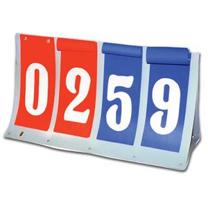
Looking for a 2 digit - seven segment display (x2) with the ability to count up and count down (4 buttons)

Similar to this display -

Can I incorporate a 4 button RF transmitter/receiver

The Design

The following figure shows a simple two digit up/down pulse counter circuit which can be used for the above requested application.

The incorporation of the specific digital ICs make the design extremely straightforward to configure and operate for the desired pulse counting display.

The IC1 and IC3 form the actual counter chips, whose BCD outputs are appropriately translated into the required 7 segment digital display outputs.

Circuit Diagram

Remote Controlled Game Scoreboard Circuit

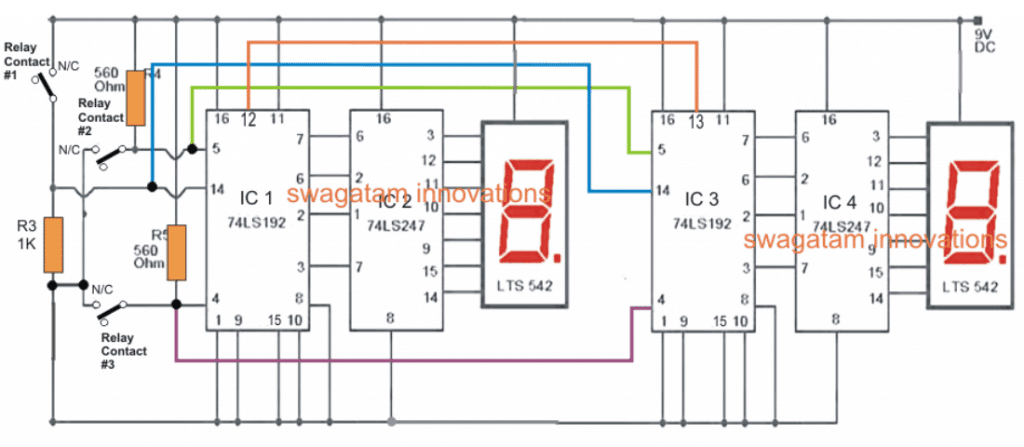
Pin#5 and pin#4 of the 74LS192 are rigged as the UP and DOWN sensing inputs, and the relevant switches when operated allow these pins to get the specified logic zero pulses for displaying the corresponding incrementing or reversing numbers on the associated 7 segment display modules.

The switch at pin#14 of the ICs is used for resetting the displays to zero with a single operation.

Since the proposed digital game scoreboard circuit is supposed to be controlled with a remote control unit, the switches at pin#5, 4 and 14 can be seen replaced with the relay contacts from the remote receiver unit.

Therefore when the compatible or matching buttons on the remote transmitter handset are pressed, the corresponding relay contacts close causing the relevant number to appear on the display board either in the ascending or descending order depending on which button was toggled.

That implies, this remote controlled game scoreboard circuit can be operated using a remote control from anywhere within the stipulated range by any member of the team simply with a press of a button of the transmitter module. And this can be done while the user enjoys the game on his/her preferred place of the ground.

The Remote Control Circuit

The remote control circuit for the discussed digital game scoreboard has been already covered in quite many articles from this website, so I won't be discussing it separately here.

The following 4 channel RF remote control circuit could be applied for the above explained circuit.

Simple RF Remote Control Circuit without Microcontroller

A little pondering reveals that the relays can be actually avoided and the output pins of the receiver RF module could be directly configured with the pin#4, 5 of the of the up/down counter IC, and the reset pin through a NPN buffer.
Alternatively, the 4 channel remote control module could be purchased ready made from the market, and in that case the existing relay contacts in the receiver unit could be wired as already suggested in this article.

The colored lines in the proposed remote controlled game scoreboard diagram indicate how two counter modules are cascaded between each other, more digits could be included by simply cascading more such IC stages in similar fashion.

You'll also like:

  • 1.  Remote Controlled Fish Feeder Circuit – Solenoid Controlled
  • 2.  Multiple Appliances Remote Control Circuit
  • 3.  Remote Controlled Wireless Water Level Controller Circuit
  • 4.  Firecracker Igniter circuit [Remote Controlled with Timer]
  • 5.  Remote Controlled Trolley Circuit without Microcontroller
  • 6.  Quadcopter Remote Control Circuit without MCU

About Swagatam

I am an electronic engineer (dipIETE ), hobbyist, inventor, schematic/PCB designer, manufacturer. I am also the founder of the website: https://www.homemade-circuits.com/, where I love sharing my innovative circuit ideas and tutorials.
If you have any circuit related query, you may interact through comments, I'll be most happy to help!

Subscribe for the Latest Posts


Reader Interactions

Comments

    Your Comments are too Valuable! But please see that they are related to the above article, and are not off-topic! Cancel reply

    Your email address will not be published. Required fields are marked *

  1. Unknown says

    Hi Sir,

    I have been working on the mosquito swatter bat circuit and I have rigged up the circuit in LTspice. Please guide me in how to test the circuit and also the turns of transfromer.

    Reply
  2. Henrik Lauridsen says

    Hi Swagatam,

    I have difficulties to find the 74LS247.
    Can the 74LS192 and the 74LS247 be replaced by CD4510 and CD4511 or other CD40xx?

    Thank you,
    Henrik

    Reply
    • Swagatam says

      Hi Henrik, 74LS247 can be replaced with 4511 but 74LS192 cannot be replaced with 4510 because the two are entirely different type of ICs….74LS192 does not depend on a separate clock input for the counting, whereas 4510 does require.

      Reply
    • Swagatam says

      …I don't think there's any other direct replacement expect 74192, which is an old version of the same

      Reply
  3. Henrik Lauridsen says

    Hi Swagatam, thank you for your fast reply.
    I have found the 74LS192 in China and am looing forward to build your circuit.

    Reply
    • Swagatam says

      That's great Henrik, I wish you all the best!!

      Reply

Primary Sidebar


Categories

  • 3-Phase Power (15)
  • 324 IC Circuits (19)
  • 4017 IC Circuits (53)
  • 4060 IC Circuits (25)
  • 555 IC Circuits (98)
  • 741 IC Circuits (19)
  • Amplifiers (58)
  • Arduino Engineering Projects (82)
  • Audio Projects (95)
  • Battery Chargers (82)
  • Car and Motorcycle (94)
  • Datasheets (46)
  • Decorative Lighting (Diwali, Christmas) (33)
  • DIY LED Projects (89)
  • Electronic Components (97)
  • Electronic Devices and Circuit Theory (35)
  • Electronics Tutorial (109)
  • Fish Aquarium (5)
  • Free Energy (35)
  • Fun Projects (11)
  • GSM Projects (9)
  • Health Related (18)
  • Heater Controllers (28)
  • Home Electrical Circuits (101)
  • How to Articles (20)
  • Incubator Related (6)
  • Industrial Electronics (28)
  • Infrared (IR) (40)
  • Inverter Circuits (98)
  • Laser Projects (12)
  • LM317/LM338 (21)
  • LM3915 IC (25)
  • Meters and Testers (63)
  • Mini Projects (171)
  • Motor Controller (66)
  • MPPT (7)
  • Oscillator Circuits (24)
  • PIR (Passive Infrared) (8)
  • Power Electronics (33)
  • Power Supply Circuits (74)
  • Radio Circuits (9)
  • Remote Control (47)
  • Security and Alarm (61)
  • Sensors and Detectors (116)
  • SG3525 IC (5)
  • Simple Circuits (74)
  • SMPS (29)
  • Solar Controllers (61)
  • Timer and Delay Relay (54)
  • TL494 IC (5)
  • Transformerless Power Supply (8)
  • Transmitter Circuits (40)
  • Ultrasonic Projects (14)
  • Water Level Controller (45)

Circuit Calculators

  • AWG to Millimeter Converter
  • Battery Back up Time Calculator
  • Capacitance Reactance Calculator
  • IC 555 Astable Calculator
  • IC 555 Monostable Calculator
  • Inductance Calculator
  • LC Resonance Calculator
  • LM317, LM338, LM396 Calculator
  • Ohm’s Law Calculator
  • Phase Angle Phase Shift Calculator
  • Power Factor (PF) Calculator
  • Reactance Calculator
  • Small Signal Transistor(BJT) and Diode Quick Datasheet
  • Transistor Astable Calculator
  • Transistor base Resistor Calculator
  • Voltage Divider Calculator
  • Wire Current Calculator
  • Zener Diode Calculator

Facebook
Twitter
YouTube
Instagram
My Facebook-Page
Quora

© 2022 · Swagatam Innovations

We use cookies on our website to give you the best experience.
Cookie settingsAccept All
Privacy & Cookies Policy

Privacy Overview

This website uses cookies to improve your experience while you navigate through the website. Please visit the Privacy Policy Page for more info.
Necessary
Always Enabled
Necessary cookies are absolutely essential for the website to function properly. This category only includes cookies that ensures basic functionalities and security features of the website. These cookies do not store any personal information.
Non-necessary
Any cookies that may not be particularly necessary for the website to function and is used specifically to collect user personal data via analytics, ads, other embedded contents are termed as non-necessary cookies. It is mandatory to procure user consent prior to running these cookies on your website.
SAVE & ACCEPT