This circuit is basically a simple yet extremely accurate push button monostable timer using one half of a CD4538 dual monostable multivibrator IC. It works as a one-shot timer, where one press and release of S1 produces one timed output pulse. This pulse turns ON the BC557 transistor and the LED for around 7 seconds, after which the circuit automatically returns to its normal state.

Main function of the circuit
The circuit works like this:
Press S1 then CD4538 gets triggered, then output changes state, then BC557 turns ON, then LED lights up, then after around 7 seconds LED turns OFF.
This type of circuit is called a monostable because it has one normal stable state. When the push button is operated, the circuit temporarily changes to its other state and remains there for the preset time. After the timing period is over, it automatically returns to its original stable state.
The CD4538 is a dual precision monostable, which means it has two separate one-shot timer sections. In this circuit only one section is used.
CD4538 power supply
The IC can be powered from about +5 V to +12 V.
Pin 16 = positive supply
Pin 8 = ground
These are the VDD and VSS pins.
It is also better to put a 100 nF ceramic capacitor directly between pins 16 and 8, close to the IC. This will help to keep the IC supply stable.
How S1 triggers the monostable timer
This part is slightly interesting.
- Pin 5 is the B trigger input of the first CD4538 section.
- Pin 4, the A trigger input, is connected to ground.
- Pin 3, the reset/clear input, is connected to the positive supply.
- The S1 arrangement makes pin 5 change state when the switch is operated.
- When S1 is not pressed, pin 5 is LOW.
- When S1 is pressed, pin 5 becomes HIGH.
- The IC 4538 B input responds to a falling edge, so the actual timing starts when S1 is released.
That means the operation is basically:
Press S1 so pin 5 goes HIGH.
Release S1 then pin 5 goes LOW and monostable timer starts.
So the LED starts its 7 second ON period when the button is released, not when it is pressed.
This is the normal working principle of a monostable circuit. The circuit stays in its stable state until it receives a trigger. After the trigger, it changes state for a fixed time and then automatically returns to the stable state.
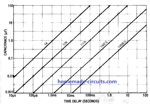
R1 and C1 are the timing components
R1 = 1.5 MΩ
C1 = 4.7 µF
These two components decide how long the output pulse remains active.
For the CD4538, the pulse width is approximately:
T = R × C
Here:
R = 1.5 MΩ
C = 4.7 µF
So:
T = 1.5 × 10^6 × 4.7 × 10^-6
T ≈ 7.05 seconds
Therefore the LED should remain ON for about 7 seconds.
The actual time will not be exactly 7.05 seconds because the electrolytic capacitor can have quite a large tolerance. The resistor and IC also have their own tolerances.
What happens inside the CD4538
Before the button is operated:
C1 is charged
Q output is LOW
Q-bar output is HIGH
BC557 is OFF
LED is OFF
When S1 is released and the falling edge triggers the CD4538, then internal latch changes state. The timing capacitor is quickly discharged internally. Then the IC allows C1 to charge again through R1.
During this charging period, the monostable output stays active. When the capacitor reaches the required internal threshold, the IC 4538 changes back to its normal state.
The output pulse therefore ends and the LED turns OFF.
This is the normal operation of a monostable timer. The important point is that the circuit does not stay in the triggered state permanently. It automatically comes back to its stable state after the timing period.
Why the circuit uses pin 7 instead of pin 6
For the first section of the CD4538:
Pin 6 = Q
Pin 7 = Q-bar, which is the inverted output.
The circuit uses pin 7 to drive the BC557 through R2.
When the timer is idle:
Q = LOW
Q-bar = HIGH
The BC557 is a PNP transistor and its emitter is connected toward the positive supply. So when its base is HIGH, the transistor remains OFF.
When the timer is triggered:
Q = HIGH
Q-bar = LOW
Therefore pin 7 goes LOW. This pulls the BC557 base down and turns the PNP transistor ON. After around 7 seconds, pin 7 goes HIGH again. The BC557 turns OFF and the LED also turns OFF. So the monostable action can be seen directly at the BC557 and LED:
Trigger, then output changes state, then LED becomes ON, then timing period expires, then output returns to normal, and finally LED turns OFF.
What R3 is doing
R3 = 1k Ω
R3 is the current limiting resistor for the LED.
The approximate LED current can be calculated as:
I_LED ≈ (V_CC - V_LED - V_CE(sat)) / R3
For example, with a 5 V supply and a red LED:
I ≈ (5 - 2 - 0.2) / 1000
I ≈ 2.8 mA
At 12 V:
I ≈ (12 - 2 - 0.2) / 1000
I ≈ 9.8 mA
For a normal indicator LED, something around 470 Ω to 1 kΩ is ok, depending on the supply voltage and how bright the LED needs to be.
R2 is the BC557 base resistor
R2 = 4.7k Ω
R2 limits the current going into the BC557 base from the IC 4538 output.
When pin 7 goes LOW, the BC557 emitter is near the positive supply while its base is pulled down through R2. So as shown something like 1 kΩ to 4.7 kΩ can be generally be very suitable for driving a normal LED with the BC557.
One important point about the unused CD4538 section
The CD4538 has two monostable sections, but this circuit uses only the first one.
The second section should not be left with floating CMOS inputs. Its unused inputs should be connected to proper fixed logic levels as recommended in the CD4538 datasheet.
How the Circuit Works Overall
So in simple words, this is a monostable or one-shot timer circuit.
The circuit normally stays in its stable OFF state. When S1 is operated and released, the CD4538 receives a trigger and changes its output state. The BC557 then turns ON and lights the LED.
R1 and C1 decide how long this state continues, which is around 7 seconds with the shown values.
After the 7 second timing period, the CD4538 automatically returns to its normal state, the BC557 turns OFF and the LED also turns OFF.
So the complete operation is:
S1 >> Trigger CD4538 >> Monostable changes state >> R1 + C1 timing starts >> Around 7 second output pulse >> Pin 7 goes LOW >> BC557 turns ON >> LED turns ON >> Around 7 seconds later >> CD4538 returns to stable state >> BC557 turns OFF >> LED turns OFF
The basic idea of this monostable timer circuit is quite simple and useful for applications where an LED or another load needs to be switched ON for a fixed time after a push button is operated.



Need Help? Please Leave a Comment! We value your input—Kindly keep it relevant to the above topic!