A joule thief circuit is basically an efficient, self-oscillating voltage booster circuit, built using a single transistor, resistor and an inductor, which can boost voltages as low as 0.4 V from any dead AAA 1.5 cell, to much higher levels.
Technically it may seem impossible to illuminate a 3.3 V LED with a 1.5V source, but the amazing concept of joule thief makes this look so easy and effective, and virtually unbelievable. Moreover the circuit additionally makes sure that not a single drop of "joule" is left unused in the cell.
A joule thief circuit is pretty popular with all electronic hobbyists, because the concept allows us to operate even the white and the blue LEDs from a 1.5V source which normally require 3V to illuminate brightly.
Design#1: Joule thief 1 watt LED Driver
The present article discusses 3 such circuits, however here we replace the traditional 5mm LED with a 1 watt LED.
The concept discussed here remains exactly identical to the usual joule thief configuration, we just replace the normally used 5mm LED with a 1 watt LED.
Of course this would mean the battery getting drained pretty much earlier than a 5mm LED, but it's still economical than using a two 1.5 cells and not including a joule thief circuit.
Let's try to understand the proposed circuity with the following points:
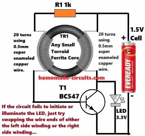
If you see the circuit diagram the only seemingly difficult part is the coil, rest of the parts are just too easy to configure. However if you have a suitable ferrite core and some spare thin copper wires, you would make the coil within minutes.
The above design may be improved further by attaching a rectifying network using a diode and a capacitor, as shown below:
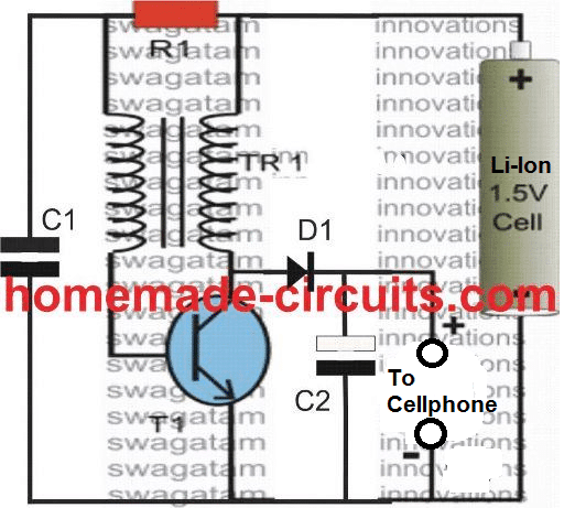
Parts List
- R1 = 1K, 1/4 watt
- C1 = 0.0047uF/50V
- C2 = 1000uF/25V
- T1 = 2N2222
- D1 = 1N4007 better if BA159 or FR107 is used
- Coil = 20 turns each side using 1 mm enameled copper wire over a ferrite ring which accommodates the winding comfortably
The coil may be wound over a T13 torroidal ferrite core using a 0.2mm or 0.3mm super enameled copper wire. About twenty turns on each side will be quite enough. In fact any ferrite core will, a ferrite rod or bar will also serve the purpose well.
After this is done, its all about fixing the parts in the shown manner.
If everything is done correctly, connecting a 1.5 V penlight cell would instantly illuminate the attached 1 watt LED very brightly.
If you find the circuit connections to be alright yet the LED not illuminating, just interchange the coil winding terminals (either the primary ends or the secondary ends) this would fix the problem immediately.
How the Circuit Functions
When the circuit is switched ON, T1 receives a biasing trigger via R1 and the associated primary winding of TR1.
T1 switches ON and pulls the entire supply voltage to ground and in the course chokes the current across the primary winding of the coil so that the biasing to T1 dries up, shutting off T1 instantaneously.
The above situation switches OFF the voltage across the secondary winding triggering a reverse emf from the coil which is effectively dumped across the connected LED. The LED illuminates!!
However the shutting of T1 instantaneously also releases the primary winding and restores it to original condition so that the supply voltage now can pass across to the base of T1. This initiates the whole process yet again and the cycle repeats at a frequency of around 30 to 50 kHz.
The connected LED also illuminates at this rate, however due to the persistence of vision we find it illuminated continuously.
Actually the LED is ON only for 50 percent of the time period, and that's what makes the unit so economical.
Also because TR1 is able to generate voltages that may be many times greater than the supply voltage, the required 3.3V to the LED is sustained even after the cell voltage has dropped to about 0.7V, keeping the LED well illuminated even at these levels.
Video Demonstration
How to wind the Torroid Coil
As can be seen in the shown joule thief circuits, the coil is ideally made over a torroid core. The details of the coil could be found in the following article. The coil structure is exactly similar and compatible with the circuits discussed on this page.
How to Calculate Joule Thief Circuit Parameters
Base Resistor (Rb) Calculation:
The formula for the base resistor ( R_b ) is:
Rb = (Vbattery - Vbe) / Ib(target)Where:
- ( Vbattery ) = 1.5V (battery voltage)
- ( Vbe ) = 0.7V (base-emitter voltage of the transistor)
- ( Ib(target) ) = 1mA (base current)
Inductor Transformer Turns Calculation:
For the primary inductor, the number of turns ( N ) can be calculated using the following formula:
L = (N2 * μ * A) / lSolve for ( N ):
N = √[(L * l) / (μ * A)]Where:
- ( L ) = 100 µH (target inductance)
- ( μ ) = 1000 * μ₀ (permeability of ferrite, where ( μ₀ = 4π × 10⁻⁷ H/m ))
- ( A ) = 2.5 × 10⁻⁶ m² (core cross-sectional area)
- ( l ) = 0.01 m (length of the magnetic path of the core)
Turns Ratio and Output Voltage:
To find the voltage output, use the turns ratio:
Vout = Vbattery * (Nprimary / Nsecondary)Where:
- ( Nprimary ) = Primary turns (calculated above)
- ( Nsecondary ) = Secondary turns (usually fewer turns than primary, e.g., 12 turns)
- ( Vbattery ) = 1.5V (battery voltage)
Transformer Voltage Ratio:
To calculate the voltage ratio between primary and secondary:
Voltage Ratio = Nsecondary / NprimaryThis gives the relationship between the input and output voltages.
Example Code for Base Resistor and Turns Calculation:
Base Resistor Calculation (Rb):
Rb = (Vbattery - Vbe) / Ib(target)
Where:
Vbattery = 1.5V, Vbe = 0.7V, Ib(target) = 0.001A

Inductor Turns Calculation:
N = √[(L * l) / (μ * A)]
Where:
L = 100 µH = 100 * 10-6 H, l = 0.01 m, μ = 1000 * μ₀ = 1.256 * 10-3 H/m, A = 2.5 * 10-6 m²

Output Voltage Calculation:
Vout = Vbattery * (Nprimary / Nsecondary)
Where:
Nprimary = 57 (calculated primary turns), Nsecondary = 12 (example secondary turns)

Voltage Ratio:
Voltage Ratio = Nsecondary / Nprimary
Additional Explanations:
Base Resistor (Rb):
Here, for finding the base resistor, we no need to worry much because the formula is super easy and direct. We just take like this:
Rb = (Vbattery - Vbe) / Ib(target).
That means we subtract Vbe from the battery voltage then divide by the base current we want. That is all. It helps us to quickly get the exact base resistance we must use, no headache.
Inductor Turns (N):
Now when we talk about how many turns we need for the inductor then we cannot just fix any number randomly.
We have to use a proper formula which depends on few things, like inductance value we need, magnetic property of the core material and also the shape or geometry of the core.
So all these things affect how many turns we finally wind. We can play with these parameters depending on what core we are using and what goal we want to achieve from the design.
Voltage Output:
Here the output voltage depends mainly on the winding ratio. So if we want more voltage at output, then we increase the secondary turns compared to primary and if we want less voltage, then we reduce.
That means by adjusting the number of turns in both primary and secondary we can easily set the output voltage to our required level.
Example Configurations:
So like in our example code, we are using a common winding setup where we have 56 turns in the primary coil and 12 turns in the secondary coil. But these numbers are not fixed or strict.
We can change them anytime as per our circuit design or performance target. That gives us flexibility to customize the output.
Example Output:
For example if you use the following values:
Vbattery = 1.5V
Vbe = 0.7V
Ib(target) = 0.001A (1mA)
L = 100 µH
μ = 1.256 * 10-3 H/m (ferrite core permeability)
A = 2.5 * 10-6 m²
l = 0.01 m
Nprimary = 57 turns
Nsecondary = 12 turns
The calculations would look like:
Rb = (1.5 - 0.7) / 0.001
= 800 Ohms

N = √((100 * 10-6 * 0.01) / (1.256 * 10-3 * 2.5 * 10-6))
= 56.57 turns (round to 57)

Vout = 1.5 * (57 / 12)
= 7.13V (approx.)

Voltage Ratio = 12 / 57
= 0.21
This output matches the working of a basic Joule Thief circuit, which is as per our exprectations.
Overunity Circuit using Joule Thief Concept
Parts List
R1 = 1K, 1/4 watt T1 = 8050 TR1 = see text LED= 1 watt, high bright Cell = 1.5V AAA penlight
The above circuit can be also driven using a DC motor. A simple diode and a filter capacitor rectification would be enough to convert the supply from the motor suitable for illuminating the LED very brightly.
If the motor rotation is sustained with the help of a turbine/propeller arrangement and operated by wind energy, the LED can be kept illuminated continuously, absolutely free of cost.
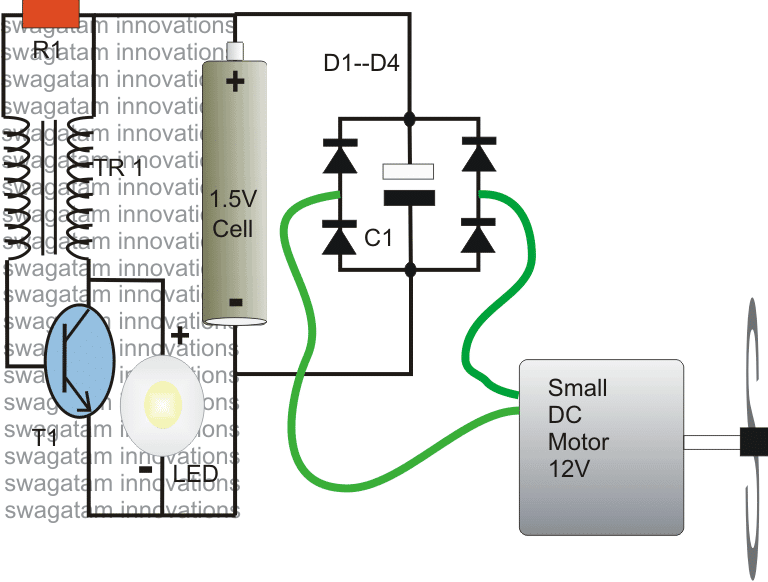
Video Demonstration
Parts List
- R1 = 1K, 1/4 watt
- T1 = 8050
- TR1 = see text
- LED= 1 watt, high bright Cell = 1.5V Ni-Cd
- D1---D4 = 1N4007
- C1 = 470uF/25V
- M1 = Small 12V DC motor with propeller
Design#2: Illuminating a Blue LED with 1.5V Cell
LEDs are getting popular day by day and are being incorporated for many applications wherever an economic lighting solution becomes an issue.
LEDs are by itself are very economic as far as power consumption is concerned, however the researches are never satisfied and they are trying hard, relentlessly to make the device yet further efficient with their power requirements.
Here's an alternate joule thief design of a simple Blue and white LED driver that works with just 1.5 volts for the illuminating 3.3V LEDs, and looks pretty amazing and too good to be true.
If we go through the datasheet of a blue or a white LED, we can easily find that these devices need a minimum of 3 volts to light up optimally.
However the present design employs just a single 1.5 V cell for producing the same as with a 3 V battery.
That’s where the whole configuration becomes very special.
The Importance of Inductor
The trick lies with the inductor L1 which in fact becomes the heart of the circuit.
The entire circuit is built around a single active component T1, which is wired up as a switch and is responsible for switching the LED at a very high frequency and at a relatively high voltage.
Thus the LED is never switched ON continuously rather stays ON only for a certain portion of the time period, however due to persistence of vision we find it switched ON permanently without any oscillation.
And because of this partial switching the power consumption also becomes partial making the consumption very economic.
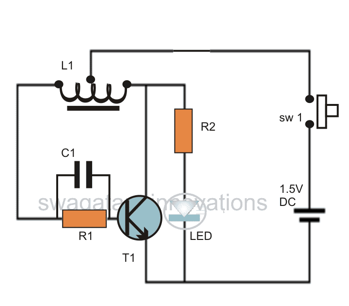
This LED Joule thief circuit may be simulated with the following points:
How it Works
As can be seen in the diagram, the circuit involves only a single transistor T1, a couple of resistors R1, R2 and the inductor L1 for the main operation.
When power is switched ON, transistor T1 is forward biased instantaneously through the left half winding of L1. This pulls the current stored inside L1 through the collector of T1 to ground which is technically twice the value of the applied supply voltage.
The grounding of L1 instantly switches off T1since the action inhibits the base bias current of T1.
However the moment T1 switches OFF, a peak voltage twice the value of the supply voltage, generated as a result of a back EMF from the coil is dumped inside the Led, illuminating it brightly.
The condition however stays only for a fraction of a second or even less when the T1 switches ON once again, because its collector is no longer pulling the base drive to ground during that instant.
The cycle keeps on repeating, switching the LED as described above at a very rapid rate.
The LED consumes a nominal 20 mA in the switched ON condition, making the whole proceeding truly efficient.
Making the Coil L1
The making of L1 is by no means difficult at all, in fact it does not carry much criticality, you may try a number of versions by varying the number of turns and by trying out different material as the core, of course they all must be magnetic by nature.
For the proposed circuit, one can use the wire from a discarded 1amp transformer. Use the secondary winding wire.
A 3 inches nail may be selected as the core over which the above wire needs to be wound.
Initially you may try winding about 90 to 100 turns over it, don’t forget to remove the center tap at 50th winding.
Alternatively, if you a have some lengths of telephone wire in your junk box, you may try it for the design.
Tear apart one of the wires from the twin section and wind it over an iron nail having a length of about 2 inches. Wind at least 50 turns and follow the procedures as explained above.
Rest of the things may be assembled with the help of the given schematic.
Switching ON power to the assembled circuit will instantly illuminate the LED and you can use the unit for any relevant desired application.
Parts List
You will require the following parts for the proposed 1.5 white/blue LED driver circuit:
- R1 = 1K5,
- R2 = 22 Ohms,
- C1 = 0.01uF
- T1 = BC547B,
- L1 = as explained in the text.
- SW1 = Push to ON switch.
- LED = 5 mm, Blue, white LED. UV LEDs can aso be driven with this circuit.
- Supply = From 1.5 penlight cell or a button cell.
Design#3: Illuminating four 1 watt LEDS with 1.5V Cell
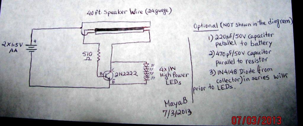
Can you imagine illuminating four numbers of 1 watt LEDs through a a few 1.5V cells? Looks quite impossible. But it can be done simply using a coil of ordinary speaker wire, a transistor, a resistor and of-course a 1.5V pencil cell.
The idea was suggested to me by one the keen followers of this blog Ms. MayaB, here are the details, I have explained them:
Circuit Operation
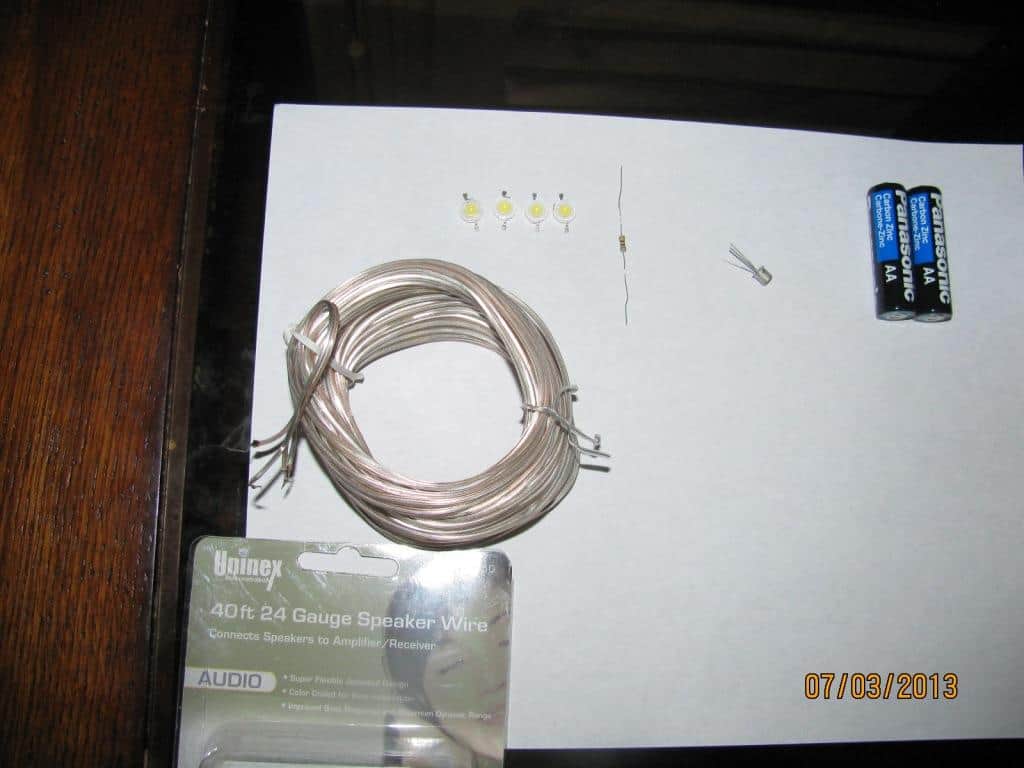
FYI, I tried this simple JT using a 40ft. paired speaker wire (24AWG) purchased at dollar store (of course, for $1).
No torroid, no ferrite rod, just simple air core wound to make it more like a coil (about 3" diameter) and tied the wire with a twistie tie (so that the wire will stay as a coil).
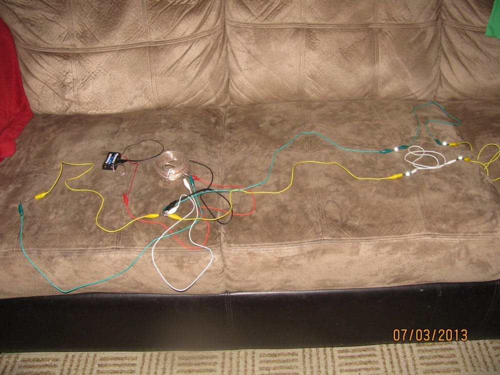
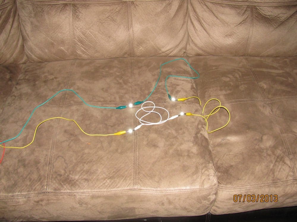
I used 2N2222 transistor, 510 ohm resistor (found out that is the best with a help of potentiometer) and was able to BRIGHTLY lit four (that is all I had) 1-watt high power LED in series (which requires same amount of current as if it was used for only one LED) using two 1.5V AA batteries (that is 3V power supply).
Can be used only one 1.5AA but will be dim (of course). I have also added a diode 1N4148 at the transistor's collecter pin just before the LED but can't tell if it increased any brightness.
Many people have used a capacitor in parallel to the battery claiming it will light the LEDs longer, I have not tested that part yet.
I have read adding a 220uF/50V electrolytic capacitor parallel to the battery would make the lights run longer, adding a 470pF/50V ceramic disc capacitor parallel to resistor will recouple the waste current in the resistor, and adding a 1N4148 diode (it is a switching diode but I don't know how would that effect the brightness) at collector of the transistor before the LEDs in series makes the LEDs brighter.
Using AAA 1.5V Cells
I don't have an oscilloscope to check all that effects. However, I would like to use rechargeable batteries instead of regular AAA 1.5V battery and make it self-regulated (or at least semi-self regulated) circuit by adding a calculator solar cell and a mini Joule Thief on a small toroid to keep charging the battery to last much-much longer.
I indeed need to add a LDR to light the LEDs only at dark and recharge the batteries during the daytime. Your suggestions and ideas are always welcome. Thanks, once again, for your interest.
Regards,
MayaB
Circuit Diagram
Prototype Images
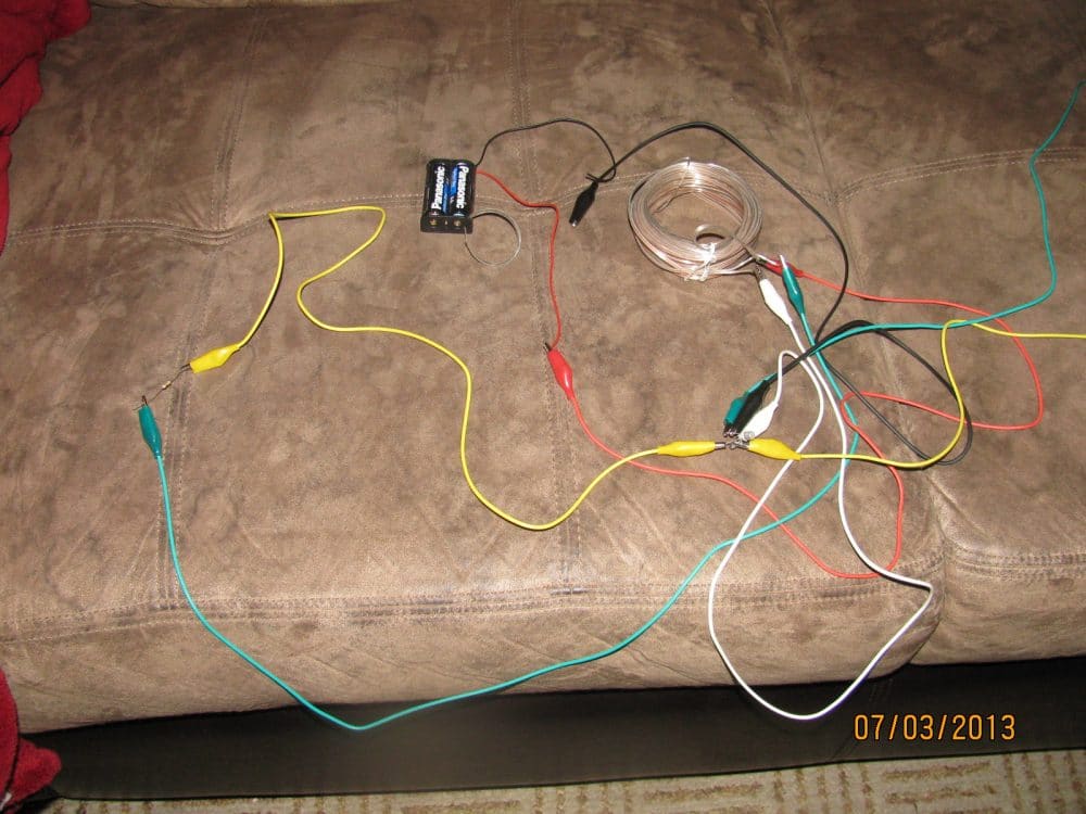
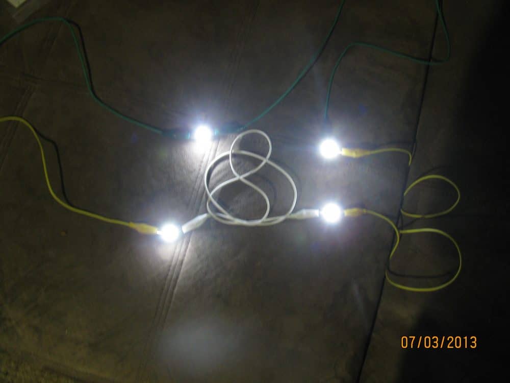
Feedback from MayaB
Hi Swagatam, Though it is long known Joule Thief circuit, not something new I discovered but thank you for posting a new article on behalf of me, I appreciated it.
Regards, MayaB
How to Improve Brightness of the LEDs
Ps. Over the weekend I hybridized your circuit with the circuit I sent you here and it turned out to be dazzling bright (warning: may blind your eyesight, hehe).
I used the same speaker wire (mentioned above), a 8050SL transistor, 2.2K resistor (paralled with a 470pf capacitor), one 1W high power LED, a 100uH choke (connected from collector of the transistor to the positive rail of power supply), and 1 diode (1N5822 connected at base of the transitor to the positive rail of the power supply).
I used two 1.5V (total of 3V) AA batteries for power supply. And btw, a LDR between 2.2K resistor and the negative rail can be added to turn the LED off during the daylight. Unfortunately, could not light more than one 1W LED with 8050SL transistor in this configuration.
Another Design for Illuminating High Power LEDs
The concept discusses yet another popular joule thief circuit, this time using power BJT 2n3055, improvised by my old friend steven in his own unique way. Let's get to the core of the developments with the following article:
In a few earlier article we covered some interesting theories summarized as given below:
- Stevens radiant joule thief battery charger circuit tests and results sunday may 9th 2010.
- The radiant joule thief circuit I built From a circuit schematic featured on a youtube video and here are the results So far
- With a aa size energizer battery, with a Measure voltage of only 1.029 volts left in it I got an output from the radiant Joule thief battery charger of 12.16 volts @14.7 milli amps.
- Test 2 using a small a23 energizer battery With a measured voltage of 9.72 volts in it I got 10.96 volts out from the circuit @0.325 milli amps.
- Test 3 I used a fully charged nimh rechargeable 9 volts battery with a measured charge of 9.19 volts dc in it and I Got 51.4 volts @137.3 milli amps output from the radiant joule thief battery Charger circuit.
- Test 4 I used a 3575a button cell battery With a measured charge of 1.36 volts in it and I got 12.59 volts out @8.30 milli amps.
- Test 5 I used an l1154 button cell battery With 1.31 volts measured in it and I got an output of 12.90 volts @7.50 milli amps.
- With an slr battery with a voltage of 12 Volts left in it I got 54.9 volts output @0.15 amps.
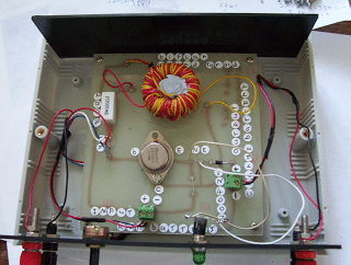
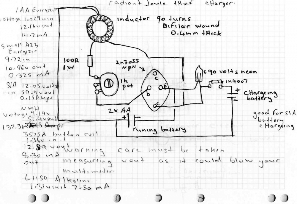
Here is the simplified drawing I built the Radiant joule thief battery charger by. The inductor I wound so many turns till It was to full to wind anymore.
But I brought 2x 5 or 6 meter lengths of Stranded copper wire unknown gauge from dicksmiths electronics insulated wire, and I wound most of it on except I think a few feet left over.
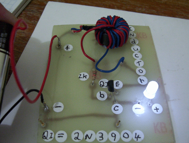
The latest test I used my pencil energizer Battery but I didn't remeasure the volts in it.
I powered the radiant energy Joule thief with it and at the outputs I put a 2200uf electrolytic capacitor Rated at 50 volts.
I ran my multimeter leads from it and got up to before I Stopped 35.8 volts , and that’s the charge being fed into the capacitor to ,
Before that I was getting 27.8 volts but as the capacitor was charging past the half way mark the voltage climb was slowing down, maybe due to the voltage from the battery getting low.
I'll have to remeasure it and do the test again in more detail.
Shorting the capacitor gave a snap noise And sparks. I tried it again charging it so far but This time I dumped the capacitor charge back into the input and this illuminated the neon for a second before the cap charge went down
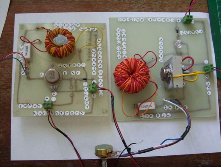
Next experiment was different I had the Outputs to my meter set to 200 millivolts range and the negative input I had my A23 energizer negative sitting on the negative input and the top positive well
My finger was on it only as for the positive input it was run to a rectangle peace of circuit Board on the end of a wire held in the air By an aligater clip.
The reading was climbing at a Faster rate I got o 47.2 millivolts before I stopped it I was getting power at
A good rate from no where with an open circuit here but I was also holding the Battery case to while doing the experiment. I just repeated these tests and got much improved results now.....
My tests will go on, and I'll keep you all updated with the latest, until then keep DIYing.
Well, these were 3 best circuits using the joule thief concept that I presented for you, if you have any more such examples please feel free to post the info through your valuable comments.
Reference: https://en.wikipedia.org/wiki/Joule_thief


Questions & Answers
Hi Tanmoy,
it will produce higher voltage at the output.
sorry NO, that won't help, you will have to use a single core for both the winding.
Hello Tanmoy,
yes, direction does matter, simply try interchanging the base and R1 wire connections of the coil, it will fix the issue.
yes, can be used.
sm, this is a very cool and circuit. is there a way we can make this a solar circuit?
yes it can be used with a solar panels for charging higher voltage batteries through lower voltage panels.
Hi Swagatam,
Can I use the coil harvested from the Quart watch, not sure of the induction it has but it has only two wires as connections. Will I be able to use any iron nail etc as ferrite core into this to work this circuit.
Regards
Gopal
Hi Gopal,
The coil needs to have two separate winding, a single winding won't help, so I am afraid the quartz coil won't do.
Yes you can use a nail as the core, but the number of turns will need to be increased from 20 on each side to 50 on each side.
What if I connect lion 3.7v battery what will be the output voltage???
and what to do to increase output??
what will be output current if input current is 1 Amp??
give me formulae for all.
sorry if I am annoying u too much 🙁
with 3.7V use 5 to 10 turns on each side and check the voltage across the LED side and increase or decrease the LED side turns for optimizing the output voltage as per the requirement.
output will be = V x I of input…always
how to increase output current??
by increasing input current
Sir u said is common sense, i knw that, how can i increase current of a battery
Rushi, current parameter is always fixed, it can decrease but never increase.
no no Sir
I am asking u how to take max uotput from this circuit
what is the max input current?
….the max output current will be slightly less than the max input current.
the wire thickness of the coil should be selected such that it is able to handle this much current
thanks
Hello sir,
This is Sherwin.
What is the total current consumption of this circuit(1st diagram schematic)?
well sir, i built this circuit in a different way;
1. i salvaged the inductor from an old computer power supply.
2. i shorted one opposite winding with respect to start of first coil and end of second coils. i connected positive 1.5v at the tap.
3. i connected the resistor from the transistors' base to the start of second coil.
4. i connected the transistors collector to end of first coil.
after making the whole circuit, i then connected a 1n4148 at the tr's collector pin and followed it with a elec. cap rated at 1000uF@25v. and finally connected the led.
The interesting part was that the led came out to be much more brighter.
with conclusions i can say that the led got a pure dc after rectifying the pulsed output.
Regards
That's great Sherwin, thanks for the update
however, brighter LEd means more consumption….because each time the capacitor charges it draws that extra bit of more current from the battery
Hi sir,
Sherwin again.
When i built the circuit without the 1n4148 and cap, a humming sound was clearly audible from the coil. I tried putting a capacitor across the bias resistor to check for any differences but the LED stopped glowing.
Why is such a thing??
Hi Sherwin, try a 0.01uf or any other lower value capacitor…and check the response
Yes sir,
i did as you said but the LED is still going off.
What next??
Could putting a 100uF10v elec.cap parallel to the input supply increase the working time.
I think the shown design is OK and there's no way you can modify it for getting greater efficiency.
Sir i need to run 1w led with lithium 18650 battery.
The fully charged voltage is 4.2v
Empty voltage cutoff is 3.0v
I'm confused with choosing current limiting resistor..
Help me with diagram..
soundarrajan, use a 1N4007 diode in series with the LED and connect it directly with the cell…no resistor is required.
But bcoz of this diode, the led terminal voltage also dropping. It ll reduce brightness .
If the led turns off at 2.7v, still my battery volt is 3.5v, i need to utilise upto 3.2v from my battery without dimming led.
Li-ion cells must never be discharged below 3.6v, and charged above 4.2V….so the suggested diode concept provides safety to the LED and the li-ion cell both together.
Sir, 3.6v is nominal voltage.
The cutoff voltage is 3v, for safety of cell, we can cutoff at 3.1 or 3.2.. That's y I'm asking
No, the safe minimum discharge level for a 3.7V li-ion cell is 3.6V or 3.5V at the most.
OK yes I confirmed it… it can be discharged upto 3V…
in that case you can use a 1.66 ohm 1/4 watt resistor instead of the diode
Dear sir,
can i use a fast recovery diode with a capacitor to convert the pulsating dc to smooth dc since mentioned frequency is between 30-50khz.
i wish to drive 2-3 multicolor leds slow changing ones.
Dear Sherwin , yes you can do it.
Hi Swagatam, I tried this circuit . It's excellent. I want to use this circuit for powerful bicycle light.I have a spare 3.7v,2800mAH Li-Ion battery and a stepper motor much bigger than the dc motor used in this circuit.I have spare LED(12v,15 W). What modification should I make 4 using those safely.
Thanks Sanjoy,
a 3.7V 2.8AH battery will be capable of handling 8 to 9 watts maximum, so I am afraid, your 15 watt LED would be a bit high for this battery.
For the circuit you may have to increase the wire thickness to around 1mm on both the sides, but make sure you use 3 or 4 strands of 0.3mm wires in parallel instead of a single 1mm wire, and also the transistor will need to be upgraded to a TIP 122 or any other similar…
Thank you for your reply Swagatam.
I will try as you said. I will post the result definitely. Btw If I use 2 Li-Ion batteries (with different mAH/ AH values same voltage) will it be able to light up the LEDs with full voltage? Should I use heat sink for the transistor and overcharge protection for the batteries in case of continuous cycling for 3-4 hrs with the circuit on?
yes, with another Li-ion battery you may be able to light up the LED brightly, the battery does not need to be identical in terms of AH rating.
for 3, 4 hours you will at least a 5AH battery….heatsink is compulsory for the LEDs, and also a current controller, as explained here:
https://www.homemade-circuits.com/2013/06/universal-high-watt-led-current-limiter.html
I modified the coil and used TIP 122 transistor. With a single Li-Ion now the LEDs achieved 50-60% of their full brightness I guess. I am yet two include the current limiter circuit. But before I include that and complete the project
there is one issue that needs to be sorted out. In the original circuit you used a small dc motor with two terminals whereas I am using a stepper motor with six terminals. I identified the current generating pairs(2 nos.) of the stepper.
But I could use only a single pair as I followed the original circuit wiring and left the other pair unused. I have no idea how to wire two pairs of terminals of the stepper in the circuit. So I am not able to use the full potential of the stepper.
Please show how to wire two pairs of terminal together.
I have no idea how to do it, I think you should change the motor with a two wire type, because using all the 6 wires could make the design complex….you can refer to the following article for more help:
digital.ni.com/public.nsf/allkb/C4A024DA9F197E6286257BC8005DC236
…put more wires in parallel on the LED side of the transformer…reduce the number of turns on both sides…you may try 5 turns on the primary and 7 turns on the secondary
dear sir, you are giving fantastic ideas.i want some help from u. i want a circuit for 3.3vdc to 5vdc 2amp current boost converter. 5v output must be constant (like in smps)any feed back circuit needed for this? please try to give full circuit for me.circuit without induct or is preferable. if it is compulsory we can use no problem.
thanks in advance
Thanks Nivas, you can easily modify the above concept for your application need.
for the transistor use TIP142, for the transformer initially go with 5 turns on each side. check the output voltage if it's less than 5V you can increase the secondary turns a bit and vice versa.
the wires could be a 23 SWG rated or many 30SWG in parallel.
for feedback you can use a BC547 between the base emitter of TIP142, and link the base of the BC547 with the transformer output via a 6V zener, this will take care of the stabilization issue.
Thank u sir. Can i use tl431 for stabilization?
yes you can use TL431, ideally with an optocoupler
I have a 12 volts 5a alternator, but I want to improve the amperage of the alternator to fast charge the battery with was fitted to my bike both of them, can you suggest me a circuit wihch was full fill my requirment
I don't think current can be increased because it is dependent on the wire thickness of the alternator which cannot be changed.
however by increasing rotational speed of the alternator, the voltage output can be increased which in turn could be transformed into current through a suitable transformer or a buck converter circuit.
can show a tutorial video or a help with a link to make a coil
I have posted the videos in the above article, you can see how the coil is wound over a ferrite torroid
good day sir
can this project to be used as free energy generator by coupling a motor and generator so that a continues rotation can happen?
john
John, sorry I don't have much idea about it….
Hello Mr.Swagatam!
coincidentally I saw a table Lamp design in youtube.The circuit design is very interesting for me.
I know you can explain it in a best way.I shall be grateful if you find a time to watch this video