• Skip to main content
  • Skip to primary sidebar

Homemade Circuit Projects

Need circuit help? Post them in the comments! I've answered over 50,000!

Blog | Categories | About | Hire Me | Contact | Calculators-online
You are here: Home / Lamps and Lights / Joule Thief Circuit using a Single Winding Inductor

Joule Thief Circuit using a Single Winding Inductor

Last Updated on October 30, 2026 by Swagatam Leave a Comment

Normally we find Joule Thief Circuits using a toroidal ferrite core with two separate winding, meaning it has a separate primary and secondary winding just like transformers. However, in the article we will discuss about a design which eliminate the requirement of having two separate winding, rather makes use of a single continuous winding with a center tap.

Table of Contents
  • The Importance of Inductor
    • How it Works
    • Making the Coil L1
      • Parts List

This alternate joule thief design can be identically used to drive Blue and white LEDs that works with just 1.5 volts or for illuminating all 3.3V LEDs, and it looks pretty amazing and too good to be true.

If we go through the datasheet of a blue or a white LED, we can easily find that these devices need a minimum of 3 volts to light up optimally.

However the present design employs just a single 1.5 V cell for producing the same as with a 3 V battery.

That’s where the whole configuration becomes very special.

The Importance of Inductor

The trick lies with the inductor L1 which in fact becomes the heart of the circuit.

The entire circuit is built around a single active component T1, which is wired up as a switch and is responsible for switching the LED at a very high frequency and at a relatively high voltage.

Thus the LED is never switched ON continuously rather stays ON only for a certain portion of the time period, however due to persistence of vision we find it switched ON permanently without any oscillation.

And because of this partial switching the power consumption also becomes partial making the consumption very economic.
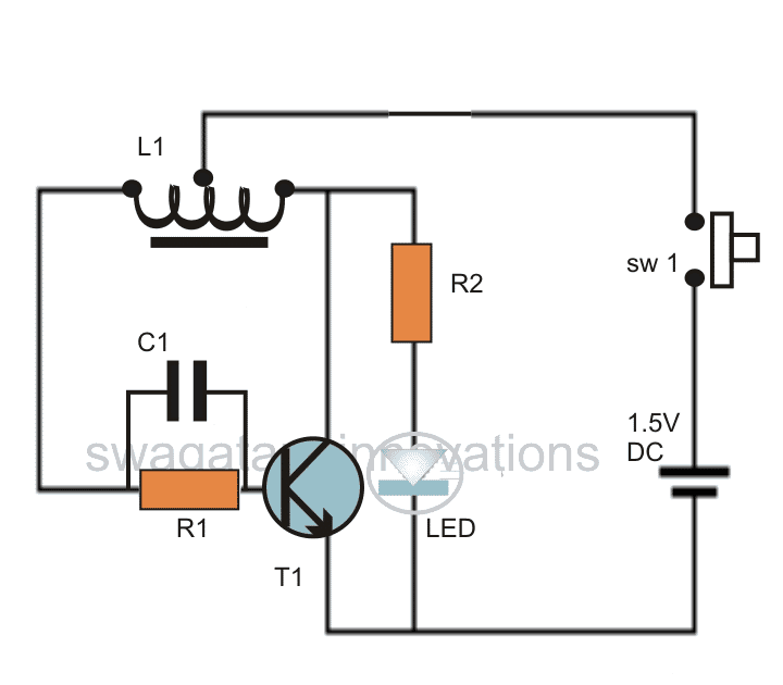
very simple joule thief circuit diagram

This LED Joule thief circuit may be simulated with the following points:

How it Works

As can be seen in the diagram, the circuit involves only a single transistor T1, a couple of resistors R1, R2 and the inductor L1 for the main operation.

When power is switched ON, transistor T1 is forward biased instantaneously through the left half winding of L1. This pulls the current stored inside L1 through the collector of T1 to ground which is technically twice the value of the applied supply voltage.

The grounding of L1 instantly switches off T1since the action inhibits the base bias current of T1.

However the moment T1 switches OFF, a peak voltage twice the value of the supply voltage, generated as a result of a back EMF from the coil is dumped inside the Led, illuminating it brightly.

The condition however stays only for a fraction of a second or even less when the T1 switches ON once again, because its collector is no longer pulling the base drive to ground during that instant.

The cycle keeps on repeating, switching the LED as described above at a very rapid rate.

The LED consumes a nominal 20 mA in the switched ON condition, making the whole proceeding truly efficient.

Making the Coil L1

The making of L1 is by no means difficult at all, in fact it does not carry much criticality, you may try a number of versions by varying the number of turns and by trying out different material as the core, of course they all must be magnetic by nature.

For the proposed circuit, one can use the wire from a discarded 1amp transformer. Use the secondary winding wire.

A 3 inches nail may be selected as the core over which the above wire needs to be wound.

Initially you may try winding about 90 to 100 turns over it, don’t forget to remove the center tap at 50th winding.

Alternatively, if you a have some lengths of telephone wire in your junk box, you may try it for the design.

Tear apart one of the wires from the twin section and wind it over an iron nail having a length of about 2 inches. Wind at least 50 turns and follow the procedures as explained above.

Rest of the things may be assembled with the help of the given schematic.

Switching ON power to the assembled circuit will instantly illuminate the LED and you can use the unit for any relevant desired application.

Parts List

You will require the following parts for the proposed 1.5 white/blue LED driver circuit:

  • R1 = 1K5,
  • R2 = 22 Ohms,
  • C1 = 0.01uF
  • T1 = BC547B,
  • L1 = as explained in the text.
  • SW1 = Push to ON switch.
  • LED = 5 mm, Blue, white LED. UV LEDs can aso be driven with this circuit.
  • Supply = From 1.5 penlight cell or a button cell.

You'll also like:

  • torchdiaSimple Faraday Flashlight – Circuit Diagram and Working
  • 555 voltage doubler7 Easy Voltage Doubler Circuits Discussed
  • Making a Automatic 40 Watt LED Solar Street Light Circuit
  • mppt 2Single LM317 based MPPT Simulator Circuit

Filed Under: Lamps and Lights, SMPS and Converters Tagged With: Inductor, Joule, Single, Thief, Winding

About Swagatam

I am an electronics engineer and doing practical hands-on work from more than 15 years now. Building real circuits, testing them and also making PCB layouts by myself. I really love doing all these things like inventing something new, designing electronics and also helping other people like hobby guys who want to make their own cool circuits at home.

And that is the main reason why I started this website homemade-circuits.com, to share different types of circuit ideas..

If you are having any kind of doubt or question related to circuits then just write down your question in the comment box below, I am like always checking, so I guarantee I will reply you for sure!

Previous Post: « Illuminating four 1 watt LEDS with 1.5V Cell using Joule Thief Circuit
Next Post: Can we Power a Joule Thief Circuit with a Small DC Motor »

Reader Interactions

Need Help? Please Leave a Comment! We value your input—Kindly keep it relevant to the above topic! Cancel reply

Your email address will not be published. Required fields are marked *

Primary Sidebar

Categories

  • Arduino Projects (95)
  • Audio and Amplifier Projects (134)
  • Automation Projects (18)
  • Automobile Electronics (104)
  • Battery Charger Circuits (90)
  • Datasheets and Components (109)
  • Electronics Theory (153)
  • Energy from Magnets and Earth (43)
  • Games and Sports Projects (11)
  • Grid and 3-Phase (20)
  • Health related Projects (27)
  • Home Electrical Circuits (13)
  • Indicator Circuits (16)
  • Inverter Circuits (105)
  • Lamps and Lights (183)
  • Meters and Testers (72)
  • Mini Projects (28)
  • Motor Controller (68)
  • Oscillator Circuits (30)
  • Pets and Pests (15)
  • Power Supply Circuits (92)
  • Remote Control Circuits (50)
  • Security and Alarm (65)
  • Sensors and Detectors (113)
  • SMPS and Converters (52)
  • Solar Controller Circuits (63)
  • Temperature Controllers (44)
  • Timer and Delay Relay (51)
  • Voltage Control and Protection (44)
  • Water Controller (37)
  • Wireless Circuits (31)

People also Search

555 Circuits | 741 Circuits | LM324 Circuits | LM338 Circuits | 4017 Circuits | Ultrasonic Projects | SMPS Projects | Christmas Projects | MOSFETs | Radio Circuits | Laser Circuits | PIR Projects |

My YouTube Channel

Circuit Simulator: Draw and Simulate Schematics

circuit simulator image

Subscribe to get New Circuits in your Email

Other Links

  • Privacy Policy
  • Cookie Policy
  • Disclaimer
  • Copyright
  • Videos
  • Sitemap

Recent Comments

  • Swagatam on Make this 3.3V, 5V, 9V SMPS Circuit
  • Madhav Pandey on Make this 3.3V, 5V, 9V SMPS Circuit
  • Swagatam on EGS002 Datasheet, Circuit Diagram Explained
  • Do Hung on EGS002 Datasheet, Circuit Diagram Explained
  • Swagatam on Simple Timer Circuit Using IC 4060

Social Profiles

  • Twitter
  • YouTube
  • Instagram
  • Pinterest
  • My Facebook-Page
  • Stack Exchange
  • Linkedin

Calculators

  • ZVS Induction Heater + Tank Calculator Tool
  • Zener Diode Calculator
  • Wire Current and Thickness Calculator (Ampacity Calculator)
  • Resistive Voltage Divider Calculator
  • Transistor Base Resistor Calculator
  • Transistor Astable Multivibrator Calculator
  • TL431 Calculator
  • Solar Panel, Inverter, Battery Calculator
  • Ferrite Core Air Gap Calculator Tool
  • Parallel MOSFET Calculator Tool: How to Connect MOSFETs in Parallel Safely
  • LC Resonance Calculator for EV Battery Charger Circuits
  • LED String Series Resistor Calculator
  • PFC (Power Factor Correction) Calculator Tool: 3kW
  • Passive Power Factor Correction (PFC) Calculator
  • LM567 IC Calculator Tool
  • SMPS Flyback Boost Converter Calculator
  • Shunt Resistor Calculator for Ammeters
  • SCR and Triac Gate Resistor Calculator
  • Battery Back up Time Calculator
  • Boost Converter Calculator (Non-Isolated)
  • Bootstrap Capacitor Calculator
  • Buck Converter Calculator
  • Buck-Boost Converter Calculator
  • Capacitance Reactance Calculator
  • DCM Flyback Transformer & Wire Gauge Wire Size Calculator Tool
  • Filter Capacitor Calculator
  • IC 4047 Calculator (Frequency and PWM)
  • IC 4060 Calculator
  • IC 555 Astable Calculator
  • IC 555 Monostable Calculator
  • IC SG3525, SG3524 Calculator
  • Inductance Calculator
  • Induction Heater Inductor and Resonant Frequency Calculator
  • Induction Heater Work Coil Calculator
  • Inverter LC Filter Calculator
  • LC Resonance Calculator
  • LED Current Calculator
  • LM317, LM338, LM396 Calculator
  • NAND/NOT Gate RC Values Calculator
  • NOT, NAND Gate Frequency Calculator
  • Notch Filter Calculator Tool
  • Ohm’s Law Calculator
  • Phase Angle Phase Shift Calculator
  • Power Factor (PF) Calculator
  • RC Filter Calculator
  • Reactance Calculator
  • Sine Table Calculator for SPWM Arduino Code
  • Small Signal Transistor(BJT) and Diode Quick Datasheet
  • SMPS Calculator for Toroidal Ferrite Transformers
  • SMPS Flyback Transformer Calculator – Design by Target Duty Cycle
  • TL431 Calculator
  • Op-Amp Hysteresis Resistor Calculator

© 2026 · Swagatam Innovations