• Skip to main content
  • Skip to primary sidebar

Homemade Circuit Projects

Need circuit help? Post them in the comments! I've answered over 50,000!

Blog | Categories | About | Hire Me | Contact | Calculators-online
You are here: Home / Lamps and Lights / Illuminating four 1 watt LEDS with 1.5V Cell using Joule Thief Circuit

Illuminating four 1 watt LEDS with 1.5V Cell using Joule Thief Circuit

Last Updated on October 30, 2026 by Swagatam Leave a Comment

Can you imagine illuminating four numbers of 1 watt LEDs through a a few 1.5V cells? Looks quite impossible. But it can be done simply using a coil of ordinary speaker wire, a transistor, a resistor and of-course a 1.5V pencil cell.

Table of Contents
  • Circuit Operation
    • Using AAA 1.5V Cells
    • Circuit Diagram
    • Prototype Images
    • Feedback from MayaB
      • How to Improve Brightness of the LEDs

The idea was suggested to me by one the keen followers of this blog Ms. MayaB, here are the details, I have explained them:

Circuit Operation

FYI, I tried this simple JT using a 40ft. paired speaker wire (24AWG) purchased at dollar store (of course, for $1).

No torroid, no ferrite rod, just simple air core wound to make it more like a coil (about 3" diameter) and tied the wire with a twistie tie (so that the wire will stay as a coil).

I used 2N2222 transistor, 510 ohm resistor (found out that is the best with a help of potentiometer) and was able to BRIGHTLY lit four (that is all I had) 1-watt high power LED in series (which requires same amount of current as if it was used for only one LED) using two 1.5V AA batteries (that is 3V power supply).

Can be used only one 1.5AA but will be dim (of course). I have also added a diode 1N4148 at the transistor's collecter pin just before the LED but can't tell if it increased any brightness.

Many people have used a capacitor in parallel to the battery claiming it will light the LEDs longer, I have not tested that part yet.

I have read adding a 220uF/50V electrolytic capacitor parallel to the battery would make the lights run longer, adding a 470pF/50V ceramic disc capacitor parallel to resistor will recouple the waste current in the resistor, and adding a 1N4148 diode (it is a switching diode but I don't know how would that effect the brightness) at collector of the transistor before the LEDs in series makes the LEDs brighter.

Using AAA 1.5V Cells

I don't have an oscilloscope to check all that effects. However, I would like to use rechargeable batteries instead of regular AAA 1.5V battery and make it self-regulated (or at least semi-self regulated) circuit by adding a calculator solar cell and a mini Joule Thief on a small toroid to keep charging the battery to last much-much longer.

I indeed need to add a LDR to light the LEDs only at dark and recharge the batteries during the daytime. Your suggestions and ideas are always welcome. Thanks, once again, for your interest.

Regards,

MayaB

Circuit Diagram
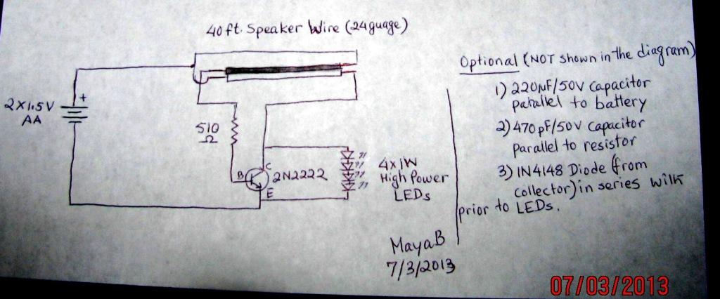
joule thief pictorial diagram for illuminating 4 nos of 1 watt LED using a 1.5V battery

Prototype Images

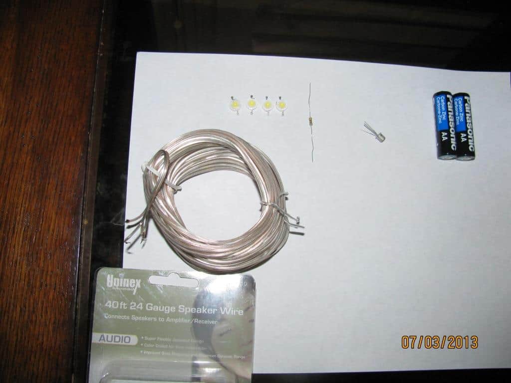
parts for joule thief circuit for illuminating 4 nos of 1 watt LED using a 1.5V battery
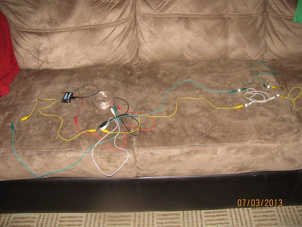
joule thief prototype showing the connection details for illuminating 4 nos of 1 watt LED using a 1.5V battery
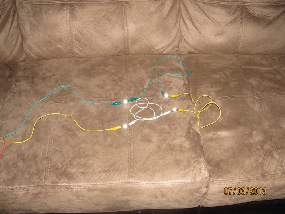
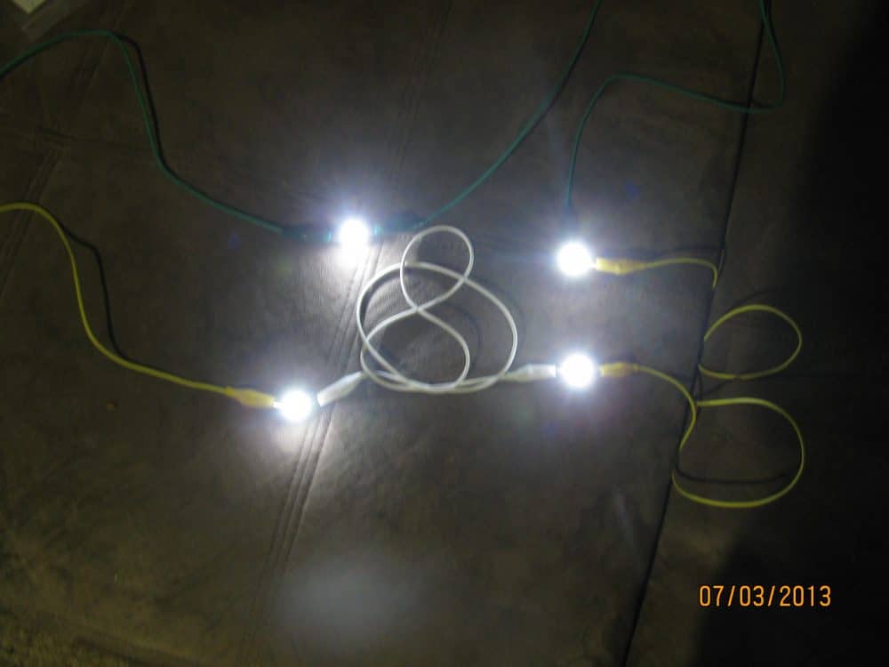
joule thief prototype showing the working of illuminated 4 nos of 1 watt LED using a 1.5V battery
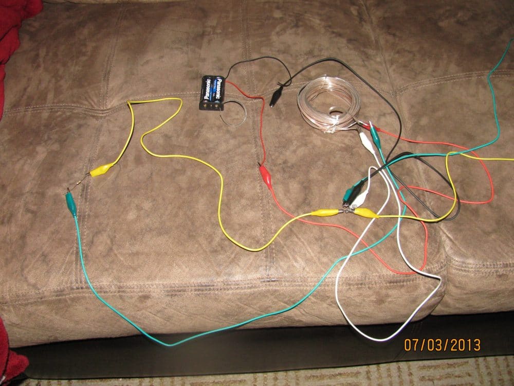
joule thief prototype showing the working of illuminated 4 nos of 1 watt LEDs in darkness using a 1.5V battery

Feedback from MayaB

Hi Swagatam, Though it is long known Joule Thief circuit, not something new I discovered but thank you for posting a new article on behalf of me, I appreciated it.

Regards, MayaB

How to Improve Brightness of the LEDs

Ps. Over the weekend I hybridized your circuit with the circuit I sent you here and it turned out to be dazzling bright (warning: may blind your eyesight, hehe).

I used the same speaker wire (mentioned above), a 8050SL transistor, 2.2K resistor (paralled with a 470pf capacitor), one 1W high power LED, a 100uH choke (connected from collector of the transistor to the positive rail of power supply), and 1 diode (1N5822 connected at base of the transitor to the positive rail of the power supply).

I used two 1.5V (total of 3V) AA batteries for power supply. And btw, a LDR between 2.2K resistor and the negative rail can be added to turn the LED off during the dayli

You'll also like:

  • simplestautomaticemergencylightcircuitusingIC555IC 555 Automatic Emergency Light Circuit
  • Transformerless Automatic Night Lamp Circuit
  • How to Connect Car LED Downlight: Circuit Diagram
  • cfloutputpinsConverting a Dead CFL into an LED Tubelight

Filed Under: Lamps and Lights, SMPS and Converters Tagged With: Cell, four, Illuminating, Joule, LEDs, Watt

About Swagatam

I am an electronics engineer and doing practical hands-on work from more than 15 years now. Building real circuits, testing them and also making PCB layouts by myself. I really love doing all these things like inventing something new, designing electronics and also helping other people like hobby guys who want to make their own cool circuits at home.

And that is the main reason why I started this website homemade-circuits.com, to share different types of circuit ideas..

If you are having any kind of doubt or question related to circuits then just write down your question in the comment box below, I am like always checking, so I guarantee I will reply you for sure!

Previous Post: « Joule Thief Circuit which can Illuminate any 3.3V LED or Higher
Next Post: Joule Thief Circuit using a Single Winding Inductor »

Reader Interactions

Need Help? Please Leave a Comment! We value your input—Kindly keep it relevant to the above topic! Cancel reply

Your email address will not be published. Required fields are marked *

Primary Sidebar

Categories

  • Arduino Projects (95)
  • Audio and Amplifier Projects (134)
  • Automation Projects (18)
  • Automobile Electronics (104)
  • Battery Charger Circuits (90)
  • Datasheets and Components (109)
  • Electronics Theory (153)
  • Energy from Magnets and Earth (43)
  • Games and Sports Projects (11)
  • Grid and 3-Phase (20)
  • Health related Projects (27)
  • Home Electrical Circuits (13)
  • Indicator Circuits (16)
  • Inverter Circuits (105)
  • Lamps and Lights (183)
  • Meters and Testers (72)
  • Mini Projects (28)
  • Motor Controller (68)
  • Oscillator Circuits (30)
  • Pets and Pests (15)
  • Power Supply Circuits (92)
  • Remote Control Circuits (50)
  • Security and Alarm (65)
  • Sensors and Detectors (113)
  • SMPS and Converters (52)
  • Solar Controller Circuits (63)
  • Temperature Controllers (44)
  • Timer and Delay Relay (51)
  • Voltage Control and Protection (44)
  • Water Controller (37)
  • Wireless Circuits (31)

People also Search

555 Circuits | 741 Circuits | LM324 Circuits | LM338 Circuits | 4017 Circuits | Ultrasonic Projects | SMPS Projects | Christmas Projects | MOSFETs | Radio Circuits | Laser Circuits | PIR Projects |

My YouTube Channel

Circuit Simulator: Draw and Simulate Schematics

circuit simulator image

Subscribe to get New Circuits in your Email

Other Links

  • Privacy Policy
  • Cookie Policy
  • Disclaimer
  • Copyright
  • Videos
  • Sitemap

Recent Comments

  • Swagatam on Make this 3.3V, 5V, 9V SMPS Circuit
  • Madhav Pandey on Make this 3.3V, 5V, 9V SMPS Circuit
  • Swagatam on EGS002 Datasheet, Circuit Diagram Explained
  • Do Hung on EGS002 Datasheet, Circuit Diagram Explained
  • Swagatam on Simple Timer Circuit Using IC 4060

Social Profiles

  • Twitter
  • YouTube
  • Instagram
  • Pinterest
  • My Facebook-Page
  • Stack Exchange
  • Linkedin

Calculators

  • ZVS Induction Heater + Tank Calculator Tool
  • Zener Diode Calculator
  • Wire Current and Thickness Calculator (Ampacity Calculator)
  • Resistive Voltage Divider Calculator
  • Transistor Base Resistor Calculator
  • Transistor Astable Multivibrator Calculator
  • TL431 Calculator
  • Solar Panel, Inverter, Battery Calculator
  • Ferrite Core Air Gap Calculator Tool
  • Parallel MOSFET Calculator Tool: How to Connect MOSFETs in Parallel Safely
  • LC Resonance Calculator for EV Battery Charger Circuits
  • LED String Series Resistor Calculator
  • PFC (Power Factor Correction) Calculator Tool: 3kW
  • Passive Power Factor Correction (PFC) Calculator
  • LM567 IC Calculator Tool
  • SMPS Flyback Boost Converter Calculator
  • Shunt Resistor Calculator for Ammeters
  • SCR and Triac Gate Resistor Calculator
  • Battery Back up Time Calculator
  • Boost Converter Calculator (Non-Isolated)
  • Bootstrap Capacitor Calculator
  • Buck Converter Calculator
  • Buck-Boost Converter Calculator
  • Capacitance Reactance Calculator
  • DCM Flyback Transformer & Wire Gauge Wire Size Calculator Tool
  • Filter Capacitor Calculator
  • IC 4047 Calculator (Frequency and PWM)
  • IC 4060 Calculator
  • IC 555 Astable Calculator
  • IC 555 Monostable Calculator
  • IC SG3525, SG3524 Calculator
  • Inductance Calculator
  • Induction Heater Inductor and Resonant Frequency Calculator
  • Induction Heater Work Coil Calculator
  • Inverter LC Filter Calculator
  • LC Resonance Calculator
  • LED Current Calculator
  • LM317, LM338, LM396 Calculator
  • NAND/NOT Gate RC Values Calculator
  • NOT, NAND Gate Frequency Calculator
  • Notch Filter Calculator Tool
  • Ohm’s Law Calculator
  • Phase Angle Phase Shift Calculator
  • Power Factor (PF) Calculator
  • RC Filter Calculator
  • Reactance Calculator
  • Sine Table Calculator for SPWM Arduino Code
  • Small Signal Transistor(BJT) and Diode Quick Datasheet
  • SMPS Calculator for Toroidal Ferrite Transformers
  • SMPS Flyback Transformer Calculator – Design by Target Duty Cycle
  • TL431 Calculator
  • Op-Amp Hysteresis Resistor Calculator

© 2026 · Swagatam Innovations