In this post I have explained how to build a simple white noise generator circuit which can be subsequently filtered to generate the pink noise output.
If you hear to the white noise or pink noise, you will find it exactly similar to the noise that we hear in FM radios in the absence of a radio station, or in TV sets showing only raster, in the no signal condition.
More information about pink noise can be studied in the following article:
https://en.wikipedia.org/wiki/Pink_noise
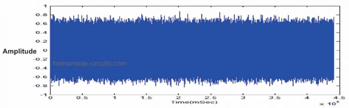
What is Noise
A noise is normally an unwanted element that can worsen the efficiency of any measuring instrument. Hence it may appear weird that any user would require the generation of such noise, however you may find this to be quite normal.
Noise generators are quite frequently accustomed to introduce noise in radio-frequency amplifiers so that it enables the user to diagnose the amplifier's low signal efficiency.
Noise generation are also found useful for checking sound systems, and like a random signal generator while introducing wind-like sound effects in music outputs. You will find a couple of widely used noise generator characteristics, which are 'pink noise' and 'white noise'.
What is White Noise
White noise is called by this name because it possesses identical noise strength in equivalent bandwidths within the entire frequency range in question. Therefore, for instance, a white noise source might possess equal energy inside the 100 to 200 Hz frequency bands upto the band of 5000 to 5100 Hz.
When the white noise goes through a filtration process or a modification, it is referred to as colored noise or, usually to be more precise it is referred to as the 'pink' or 'grey' noise.
What is Pink Noise
The definition of pink noise is usually restricted to the noise characteristic which includes identical energy per percentage change in bandwidth. For instance when a genuine pink noise is considered, the energy between 100 Hz and 200 Hz must be identical to that between 5000 Hz and 10,000 Hz (a change of 100% in each of the scenarios).
Pink noise as a result seems to possess a high degree of bass frequency compared to what the white noise may have.
Hearing the pink noise might appear a lot more consistent and stable, during the testing process.
In order to convert white noise to pink noise, it needs to go through a filtering process which causes its output level to decrease by 3 dB per octave or by 10 dB per decade, as the frequency is increased.
How the Circuit Works
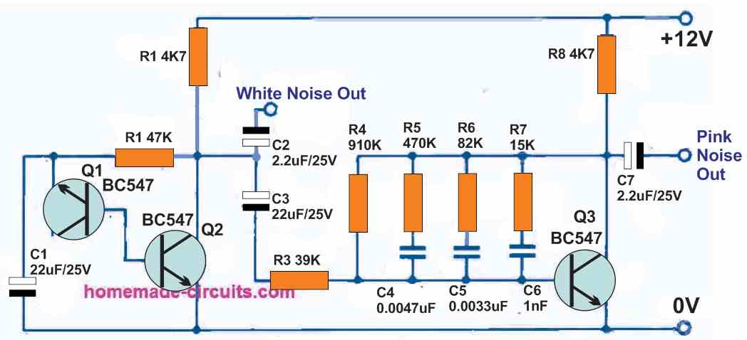
Referring to the pink noise generator circuit above, the transistor Q1 can be actually seen configured like a zener diode. The typical base-emitter junction wiring can be seen reverse-biased which gets into a zener break down situation at approximately 7 to 8 volts.
The Q1 zener noise current passes to the Q2 base, causing the generation of around 150 millivolts white noise at the output .
This `zener' configuration, no only works like a noise source, but also does the job of biasing Q2 effectively, and the Q2 noise output is applied straight to the White Noise output. To be able to transform the white noise to pink it would need to go through a filtering process, that gives a 3 dB cut per octave as the frequency is raised.
A normal RC network may not be appropriate for implementing like a individual RC stage for getting a cut of 6 dB per octave. For this reason a unique resistor Rs and capacitor Cs circuitry becomes necessary for approximating the intended 3 dB-per-octave slope.
Because this kind of a filter is able to produce a high level of attenuation of the noise, an amplifier become necessary in order to restore the output level.
For this exact reason the transistor Q3 is wired like an amplifier with the pink noise filter linked as a feedback network across the collector and base.
This enables you to get the necessary quality through the control of the gain-versus-frequency characteristics of the transistor. In this way we are able to get the required pink noise from the output of transistor Q3, which is then supplied to the indicated output socket of the circuit.
Using a Single Transistor
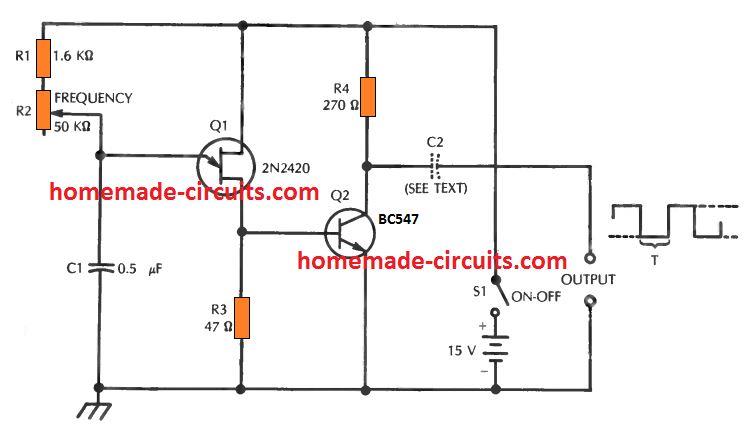
A simple white and pink noise generator could be constructed with the help of a single transistor and a Zener diode. The 10 volt Zener serves like the noise source and it furthermore stabilizes the operating level of the transistor.
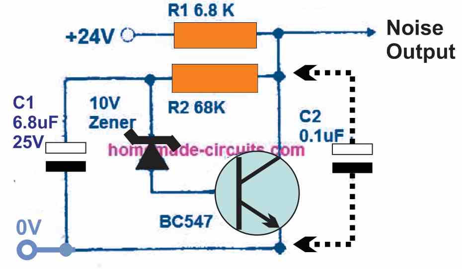
Putting a capacitor C2 at the indicated position will convert the output from 'white' noise to 'pink' noise. Using the specified components and the supply input, the white noise level of output voltage will be around 15V, and the pink noise level of output voltage around 14.5 V. The transistor could be a BC547 or any other similar small signal transistors can also work fine.

Questions & Answers
This Audio Noise Generator is directly copied with some JPEG editing to the values of C4 and C5 and also the TYPE of transistor (changed from BC548 to BC547) from the schematic for the Electronics Today International Project number ETI 441 as published in 30 Audio Projects from Electronics Today International page 144. I believe you should as least acknowledge your source. Copyright for electronics Today International publications now rests with Silicon Chip in Australia.
Thank you for notifying us about the issue. The above article and quite a few others were purchased from external sources.
I checked the silicon chip website but could not find any information regarding the Copyright being transferred from ETI to silicon chip. Please provide the link of the page where it says that ETI magazine is now silicon chip Australia, or you can directly provide the link of the page which includes the above schematics.
I would be most happy to provide the references appropriately..
The white Noise Pink Noise generator circuit is a classic and I have seen it or very similar ones in many textbooks so in my humble opinion the concept and schematic is most likely is public domain. I do own the publication I referenced but it is most likely that ETI used the circuit from another source or textbook also. I have built this circuit and can confirm it works well. Let it stand as is for the benefit of all electronics enthusiasts.
OK, thanks for the confirmation!
Hi. Can you help me design a jammet for 2500hz to 15000 hz I want to jam a Tx and Rx with 1m distance. It will serve as curtain. Please help me thank you
Hi, you can build any small MW transmitter and use it to jam the specified frequencies. I do not have the exact circuit with those frequencies at this moment.
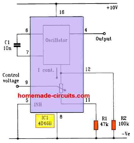
Can the last circuit be modified to produce a voltage range suitable for playing on a piezo disc or other low-EM-noise sound emitter?
yes, if another BJT stage is added to it for amplification…
Can you please make a diagram and parts list?
You can simply do in the following way:
Take a 2N2222 BJT, connect it base directly with “Noise Output”
Emitter to ground.
Piezo element between positive supply and the collector of the 2N2222.
Connect a buzzer coil in parallel with the piezo.
That’s all.
I don’t understand. I don’t know how much inductance for the inductor coil nor if it will output white noise or just buzzing.
If you put the buzzer coil then the sound output will be much louder, although it is not compulsory.
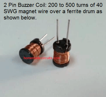
You don’t have to build that inductor, you can buy it from the market:
Will it output white noise? How many μH?
I would use a low-emissions inductor, not a linear core, but the audio would probably not be affected by that.
Yes, it will be white noise, if the base circuit functions correctly.
I have no idea about the μH of the buzzer coil, you can experiment it by winding 100 turns of super enameled copper wire over a small ferrite ring
When you buy them from the market, they normally have a 3-digit code indicating their inductance printed on the top. What value should I look for?
Buzzer coils don’t have inductance printed on them, just ask the shopkeeper to give you a buzzer coil, or show him the image, or buy it online…
tip: I looked online and found 1 seller offering a 2.2uH 2-pin buzzer coil. Many offer 3-pin buzzer coils.
You can buy the 2-pin type…
Yes, I plan to buy a 2.2μH inductor. Thanks!
Which voltage positive supply?
Try 12V first and check the response..
In the first circuit, does the first part of the circuit that directly emits white noise need additional amplification or can a direct speaker be used?
It will require an external amplifier, you can use an LM386 amplifier for the amplification…
Is the white noise generator signal suitable for modulating an RF signal?
Yes it can be used…
please describe how to apply. want to build whit , pink noise gen with r/f generator. for defense. impearative