A voltage to frequency converter circuit converts a proportionately varying input voltage int a proportionately varying output frequency.
The first design is using the IC VFC32 which is an advanced voltage to frequency converter device from BURR-BROWN specifically designed to produce an extremely proportional frequency response to the fed input voltage for a given voltage to frequency converter circuit application.
How the Device Functions
If the input voltage varies, the output frequency follows this and varies proportionately with a great degree of accuracy.
The output of the IC is in the form of an open collector transistor, which simply needs an external pull up resistor connected with a 5V source to make the output compatible with all standard CMOS, TTL and MCU devices.
The output from this IC could be expected to be highly immune to noise and with superb linearity.
The output conversion full-scale-range is determined with the inclusion of an external resistor and capacitor, which may be dimensioned to acquire a reasonably wide range of response.
Main Features of VFC32
The device VFC32 is also equipped with a feature of working in the opposite manner, that is it may be configured to work like a frequency-to-voltage converter also, with similar accuracy and efficiency. We will discuss about this in our next article in detail.
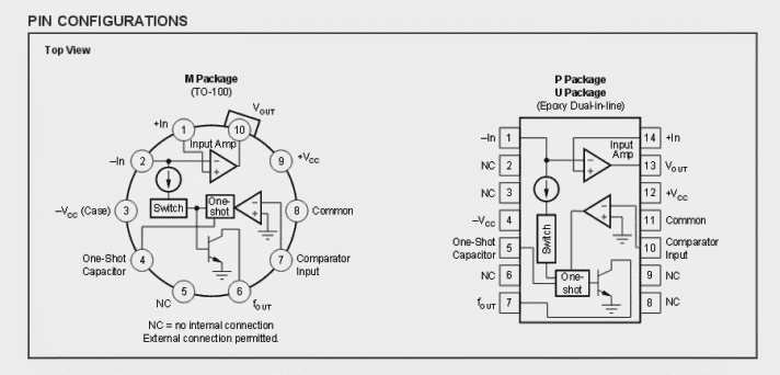
The IC may be procured in different packages as may suit your application need.
The first figure below depicts a standard voltage to frequency converter circuit configuration where R1 is used for setting up the detection range of the input voltage.
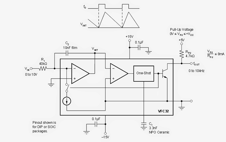
Enabling a Full Scale Detection
A 40k resistor may be selected for getting a 0 to 10V full scale input detection, other ranges could be achieved by simply solving the following formula:
R1 = Vfs/0.25mA
Preferably R1 must be an MFR type for ensuring an improved stability. By adjusting the value of R1 one may trim down the available input voltage range.
For achieving an adjustable output FSD range C1 is introduced whose value may be appropriately selected for assigning any desired output frequency conversion range, here in the figure it’s selected to give a scale of 0 to 10 kHz for an input range of 0 to 10V.
However, it must be noted that the quality of C1 may directly affect or influence the output linearity or accuracy, therefore the use of a high quality capacitor is recommended. A tantalum perhaps becomes a good candidate for this type of application field.
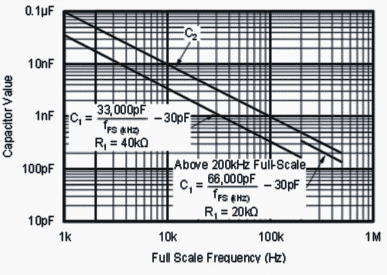
For higher ranges in the order of 200kHz and above, bigger capacitor may be opted for C1, while R1 may be fixed at 20k.
The associated capacitor C2 does not necessarily produce an impact on the functioning of C1, however the value of C2 must not cross a given limit. The value for C2 as shown in the figure below, should not be lowered, although increasing its value above this might be OK
Frequency Output
The frequency pinout of the IC is internally configured as an open collector transistor, which means that the output stage connected with this pin will experience only a sinking voltage/current (logic low) response for the proposed voltage to frequency conversion.
In order to get an alternating logic response instead of only a “sinking current” (logic low) response from this pinout, we need to connect an external pull up resistor with a 5V supply as indicated in the second diagram above.
This ensures an alternately varying logic high/low response at this pinout for the connected external circuit stage.
Possible Applications
The voltage to frequency converter circuit explained may be used for many user specific applications and could be customized for any relevant requirement. One such application could be for making a digital power meter for recording the electricity consumption for a given load.
The idea is to connect a current sensing resistor in series with the load in question and then integrate the developing current build-up across this resistor with the above explained voltage to frequency converter circuit.
Since the current build up across the sensing resistor would be proportional to the load consumption, this data would be accurately and proportionately converted into frequency by the explained circuit.
The frequency conversion could be further integrated with a IC 4033 frequency counter circuit for getting the digital calibrated readout of the load consumption, and this could be stored for future assessment.
Courtesy: http://www.ti.com/lit/ds/symlink/vfc32.pdf
2) Using IC 4151
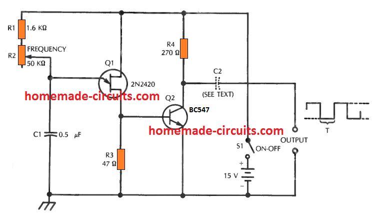
The next high performance frequency to voltage converter circuit is built around a few components and an IC based switching circuit. With the part values indicated in the schematic, the ratio of conversion is achieved with a linear response of approx. 1%. When an input voltage from 0 V-10 V is applied it gets converted to a proportionate magnitude of 0 to 10 kHz square wave output voltage.
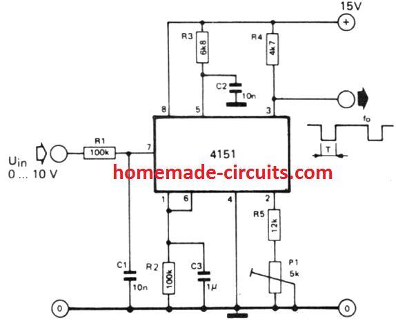
Through the potentiometer P1 , the circuit could be tweaked to ensure that an input voltage of 0 V generates an output frequency of 0 Hz. The components responsible for fixing the frequency range are resistors R2, R3, R5, P1 along with the capacitor C2.
Applying the formulae demonstrated below, the ratio of voltage to frequency conversion may be transformed in order that the circuit works extremely well for several unique applications.
While determining the product of T = 1.1.R3.C2 you must ensure that this is always below one half of the minimum output period, meaning the positive output pulse should invariably be minimum as long as the negative pulse.
f0/Uin = [0.486 . (R5 + P1) / R2 . R3 . C2 ] . [kHz/V]
T = 1.1 . R3 . C2
Questions & Answers
I currently have a sprinkler controller that has a pulse input to record flow. I would like to use that pulse input to read pressure. I have a pressure transducer that reads 0-100 PSI with a 5 vdc input and a .5-4.5 vdc output. It looks like I can adjust the liters per pulse from 500-.01.
Is there a chip that I can use directly or will I need to use a chip and a raspberry pi?
There is a device called force sensing resistor, which can be perhaps used for your application. You can read more about it here:
https://www.homemade-circuits.com/force-sensing-resistor-explained/
may i have schematic diagram? completely ug student, for project purpose
If the power supply is bipolar 15V, How to configure the VC32 to work with (-12 ~ +12) single ended input signal ?
The IC needs 15V single supply, it does not need dual supply
how can this cct work in opposite direction I.e frequency to voltage converter. I think I need it. maybe I can use it with d metal detector cct
you can refer to the following link
https://www.homemade-circuits.com/?s=frequency+to+voltage