In this post I have explained how to build a simple cricket chirping sound generator circuit using a single IC 4093 and a few other passive components.
An electronic cricket sound generator is a device which generates a sound exactly similar to a real cricket insect. This is done using a set of oscillators configured to simulate the cricket's chirping sound.
Application
Assume you've just returned from an evening spent at a friend's home. But before you leave your friends house, you hide a nasty little circuit somewhere in the house, that simulates a Cricket noise.
This little bug starts chirping, chirping, chirping as soon as the home lights are turned off (say at bedtime).
Our cricket bug also has no idea when to stop.
The chirping proceeds even while your friend stomps the floor or flings a shoe in the location of the sounds. When your friend has had enough, he or she gets up to look for the tiny demon. But as soon as the lights are turned on, there is complete quietness… no sound at all.
Basic Working Concept
Basically, the Electronic Cricket is a light-sensitive device which switches on in low-light conditions or complete darkness, but switches off as soon as subjected to full room light.
Apart from the possibility of the circuit being used in an inoffensive prank, the design can be educational since it shows how just a single 4093 IC could be used to create three electronic oscillators (two of which contribute to making the chirp sound, and the third of which works like a timer to provide a slight delay between chirps).
Circuit Description
A schematic view of the Electronic Cricket circuit is shown below. It's worth noting that the circuit is essentially a single 4093 CMOS quad two-input NAND Schmitt trigger (IC1) arranged as 3 oscillators linked sequentially, each influencing the functioning of the one before it.
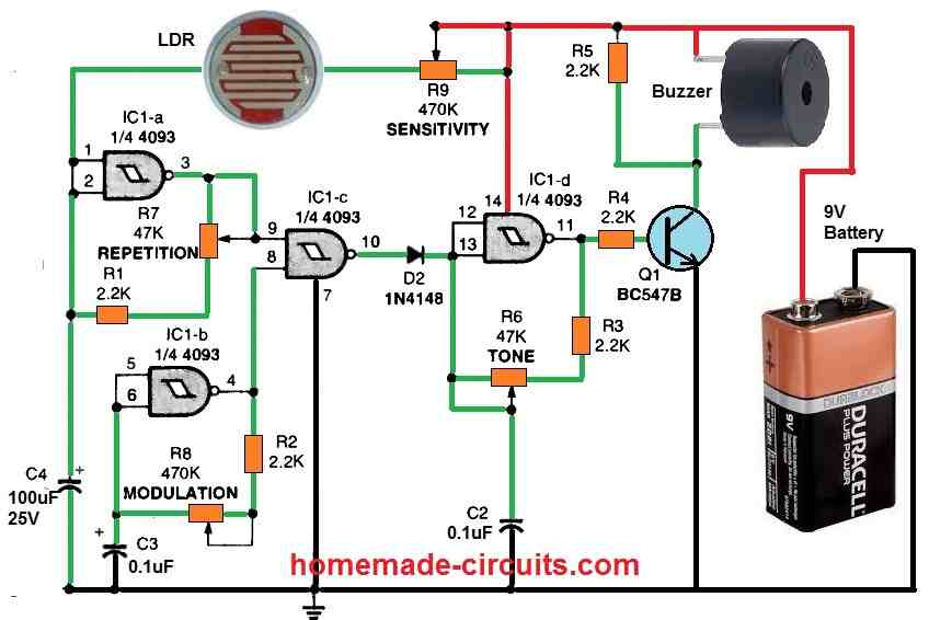
A modulation (or mixing) circuit is utilized with the 4th Schmitt trigger. The Electronic Cricket's repetition rate is controlled by the first oscillator (based on IC1a).
The combination of C4, R1, and the arrangement of R7 define the frequency of the oscillator. The speed at which the chattering sound is generated is controlled by potentiometer R7 (REPETITION).
In this implementation, a cadmium-sulfide photocell (R10), widely known as a light-dependent resistor or LDR, is linked in series with potentiometer R9 and capacitor C4, with the voltage created at the junction with the help of resistor R10 and capacitor C4. This is applied across the inputs of IC1a.
The light intensity which causes the triggering to occur is determined by potentiometer R9 (SENSITIVITY).
When the light hitting R10's LDR surface decreases to the required level, the first oscillator, along with with R10, triggers ON the circuit. The LDR R10 detects ambient illumination and has a resistance of many mega ohms in absolute darkness and a maximum resistance of about 200 ohms in full light.
The resistance across R8 begins to drop as the light intensity measured by R10 decreases. This causes the voltage provided to the inputs of IC1a to increase. As a result, the output of IC1a is forced to be low.
Due to the impact of LDR R10, the output of IC1a stays low so long as the power is switched off or is at a reduced level, just until the inputs of IC1a are dragged high through some other external source.
The low output of IC1a is split into a couple of channels. The IC1a output is fed back to its input through one channel, causing its output to flip high.
This high is sent back into the inputs of IC1a (causing C4 to charge), driving its output low yet again. This low is fed back to IC1a's inputs, enabling its output to become high yet again. That series of events continues indefinitely for long as no light is available over the LDR R10 surface.
During this time, the output of IC1a proceeds down the second channel and is fed to one of the inputs of a gating circuit (configured around IC1c).
The second oscillator output which is configured around IC1b feeds the other input to IC1c.
The second oscillator also operates in the same way as the first, except that its output switches at a different frequency, that is regulated by C3, R2, and the value of R8 (a 470K potentiometer which functions as the MODULATION control for the circuit).
In IC1c, the outputs of the two oscillators are merged to generate a third signal frequency, which is applied to the bridged inputs of IC1d.
This networks works like the third oscillator. The frequency at which the electronic cricket chirping sound is generated is determined by this third oscillator. The third oscillator output is applied to the transistor Q1 base. Q1 here functions like a switch, switching on and off at a rate set by the components R3, R6, and C2.
The signal produced by toggling Q1 triggers the buzzer ON to generate the required chirping sound. R6 (TONE) potentiometer can be used to change the amplitude of the output sound.
As soon as the lights are switched on, light radiation strikes the LDR R10, causing its resistance to drop, disabling the circuit until the area is darkened again.
Sound Controls
The proposed electronic cricket sound generator circuit has 4 distinct sound output control facilities.
- R6 = controls the tone quality of the sound output
- R7 = controls the repetition rate of the chirping sound.
- R8 = controls the modulation level of the sound.
- R9 = controls the sensitivity of the LDR, and determines at what darkness level the circuit can be triggered ON
Another Amusing Cricket Sound Simulator Circuit
Amuse your family with this intriguing gadget! This cricket sound simulator circuit can be discreetly placed in a room and will initiate enigmatic chirping sounds reminiscent of a tree frog or cricket. However, the moment you turn on the lights to locate it, the chirping ceases!
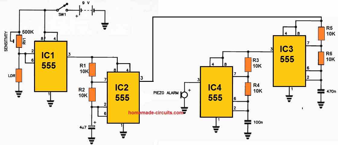
This device utilizes four 555 timer ICs. IC1 acts as a light-sensitive trigger: in darkness, the Light Dependent Resistor (LDR) exhibits high resistance, causing IC1's output to go high.
This happens because the voltage divider created with RV1 raises the trigger and threshold inputs (pins 2 and 6) of IC1.
The high output on pin 3 of IC1 supplies power to IC2, a long-period oscillator that briefly sends high pulses from its output pin every few seconds.
IC2's pin 3 output triggers IC3, a low-frequency oscillator, which subsequently modulates the activity of IC4.
IC4 generates oscillations at an audible frequency, producing the chirping sound, which occurs intermittently in accordance with the period of IC2.
When someone switches on the light to investigate the source of the noise, the LDR transitions to low resistance, pulling pins 2 and 6 of IC1 low, causing its output to go low and thereby deactivating the rest of the circuit.
The entire system is powered by a 9 V transistor radio battery, and it features a suitable piezo transducer for sound output.
If you desire a lower pitch, you can achieve this by increasing the value of the capacitor connected between pins 2 and 6 of IC4 to ground, resulting in a sound resembling more of a croak.

Questions & Answers
Would be so much better running from a 3V CR2032 coin cell. The PP9 is much harder to conceal.
CR2032 cannot handle so many LEDs, and subsequent cycles…
Can this be modified into a “Roger Beep” noise toy for my CB radio? I am looking for a roger beep that when I un-key to stop transmitting, the noise toy would hold the key open, play 2 cricket chirps, then release the key. I have very basic electronic skills and will probably be using a breadboard and through hole components.
I am not sure how a Roger Beep sound operates, however if you want the above circuits to generate 2 cricket chirp and shut off, in response to some specific input trigger, then probably that can be customized in the design.
Just completed this project. Designed and etched my own PCB too (Laser printer and Ferric Chloride). 40 years after acquiring these skills at school! It works.
Am now far removed from electronics, being a practising Consultant chest physician in the UK. It was a pleasure getting back to a childhood hobby. So thank you very much.
Will try out Paul’s suggestion of adding in a slow astable IC55 to the input, and of course some of your other circuits.
Thanks once again.
Thank you so much Milan, I hope it is working properly for you.
I really enjoyed making this circuit. I made a version with fixed resistors when I found a sound that was convincing for me. I also added a very slow 555 astable outputed to the 4093’s first gate input. That gave about 10 sec pause between chirping and I thought that sounded a bit more natural and possibly harder to locate. I look forward to seeing more circuits like this!
Thanks very much for the update Paul! Glad you could make the circuit successfully, please keep up the good work!