In this post I have explained how to build a simple whistle sound operated relay circuit, which can be used for switching ON/OFF a 220 V load through whistle sounds.
You can consider this circuit to be a whistle operated remote control circuit which will operate a connected load remotely through the sound of whistling.
Circuit Description
The whistle frequency is captured by electret-type microphone MIC1 and sent to transistor Q1 for amplification. The signal is amplified by transistor Q1 and is fed to the input of IC1, which is an LM567 PLL (phase-locked-loop) tone-decoding integrated circuit.
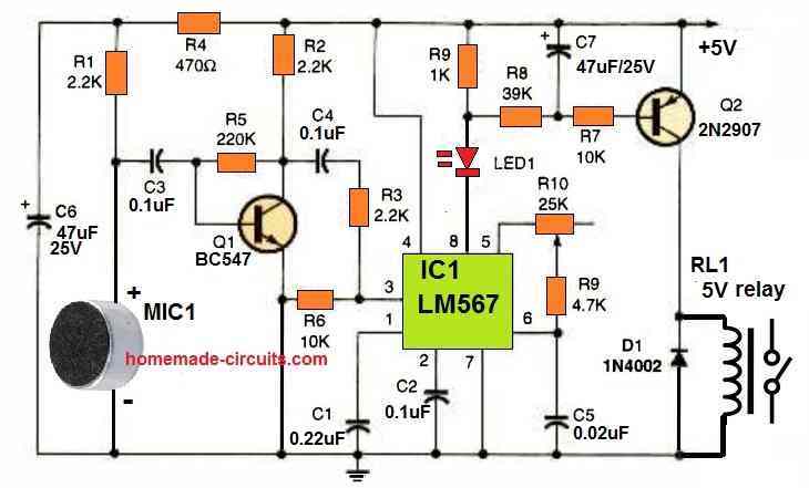
Upon identification of the whistle sound, IC1 changes its output at pin 8 to low (0V). This switches ON the LED1 and lowers the resistor R8 to almost ground potential.
A simple time-delay built around the timing components C7 and R8 prevents the relay from chattering because of voices and background noises that occur within the IC1 LM567's wavelength.
By adjusting the value of capacitor C7, the delay may be changed. A higher value means more delay, while a lower value means less delay.
For RL1, just about any 5 V SPDT relay will work as long as the coil resistance is between 200 and 500 ohms.
Consider the required load switching operation while choosing the relay's contact ratings. The part values provided should allow the circuit to detect whistle frequencies between 1 kHz and 15 kHz.
To adjust the frequency detecting tuning range of IC1, simply modify the value of capacitor C5.
For a lower frequency range, make C5 value bigger; and for a higher frequency range, make C5 value smaller.
You can use a toy whistle if you are unable to whistle or produce the same pitch repeatedly.
Parts List
- SEMICONDUCTORS
- D1- 1N4002, 1 amp, 100 PIV, general purpose rectifier diode
- IC1 - LM567 PLL tone decoder IC
- LED1 - LED, any color
- Q1 - BC547 NPN or any other NPN equivalent
- Q2 - 2N2907 PNP or any other PNP equivalent
- RESISTORS
- (All fixed resistors are 1/4 watt, 5% rated)
- R1, R2, R3 - 2.2 K
- R4 - 470 ohm
- R5 - 220 K
- R6, R7 - 10 K
- R8 - 39 K
- R9 - 4.7 K
- R10 - 25 K potentiometer
- CAPACITORS
- C1 - 0.22 uF ceramic-disc capacitor
- C2, C3, C4 - 0.1 uF, ceramic disc capacitor
- C5 - 0.02 µF, mylar, or similar capacitor
- C6, C7 - 47 uF, 25V , electrolytic capacitor
- ADDITIONAL PARTS AND MATERIALS
- MIC1- Electret-type microphone
- RL1 - 5 V relay, Whistle, cabinet, power source, etc.
Advantages
The main advantages of this whistle controlled switch circuit are as I have explained below:
- The circuit is cheap to build and use
- It can be used like a remote control for activating a load with whistle sound
- No complex transmitter handset is required.
- Requires ordinary electronic components to assemble the unit.
- The frequency of the circuit can be customized for activating with any other desired frequency.
Disadvantages
The couple disadvantages of this whistle activated switch circuit can be summarized as given below:
- Whistling may create disturbance and annoyance to the other people around.
- Anybody can activate the load using a whistling sound.



Questions & Answers
Hi, I am working on trying to repair a vintage whistle activated doll. When batteries were first put in she did do her actions. The problem is she is not supposed to do her actions until the whistle blows and she should start and stop by the whistle command. I have already put in a new transistor, capacitor and microphone. She still did the same exact thing after all those new parts were installed. There are about 8 more parts on the circuit board that could possibly be the problem. My next guess is maybe it is the resistor connected to the on switch. The colors on the resistor are tan, brown, redish pink and silver. I don’t have a multimeter yet to test all the components. Do you have a guess on what is the most likely culprit in this case to cause the malfunction? Thanks, Kimberly
Hi, I think, most likely the problem is not the resistor near ON switch. Since doll starts action immediately when battery is connected, some transistor or trigger section may be staying ON. Could be another resistor/transistor or maybe a leakage in capacitor. However, without a multimeter it may be difficult to say which is that exact part, so it would be better to first get a cheap multimeter and check voltages and resistances. It wouldn’t be a good idea to replace parts just by guessing the color codes.