In this article I have explained how to connect and use the TTP223 capacitive touch switch module. These modules work using 2.5V to 5V. They are all pre-debounced, all you need is to provide the DC supply across the VC and GND terminals, and you get an output in the middle.
So it is really that simple, you just have to give a +5V and ground, and touch the touch pad, and the output responds to your touch operations.
Main Electrical Specifications
- Operating Voltage: 2.0V to 5.5V DC
- Operating current: @VDD=3V, no load, SLRFTB=1. At low power mode typical 1.5uA, highest current usage is 3.0uA. At fast mode this is around 3.5uA and maximum current around 7.0uA@VDD=3V, no load, SLRFTB=0. At low power mode the current consumption could be around 2.0uA and a maximum of 4.0uA. While working at fast mode current intake is around 6.5uA and maximum is 13.0uA.
- Output Type: Digital (open-drain or push-pull)
- Sensitivity Adjustment: Sensitivity can be adjusted by attaching an external capacitance(0~50pF).
- Response Time: max ~ 60mS in fast mode, ~220mS at low power mode @VDD=3V
- Output Pulse Length: Specified in the datasheet
- Power Consumption: Low
- Dimensions: 15mm x 11mm
- Operating Temperature: -20 ~ +70 ℃
- Trigger Mode: Toggle or momentary
- Noise Immunity: May have noise reduction features
- Interface: VCC, GND, OUT
It Works Capacitively without Physical Touch
Actually, you don't even have to make a direct contact with the touch pad. If you put your finger pretty close to the touch pad, the output toggles ON or OFF.
That means you are able to put it behind a case, or an external cover and still switch the device ON/OFF by touching the case just above the touch pad externally, without making a physical contact with the touch pad.
TTP223 Pinout Function
Now let's take a closer look at this TTP223 capacitive touch switch module, and understand its Pinout functioning in details.
As shown below, on the flip side of the board we can see a touch pad.

Next, as shown in the next image below, if you turn the board around, it shows the labels for the various pinouts for the relevant connections.
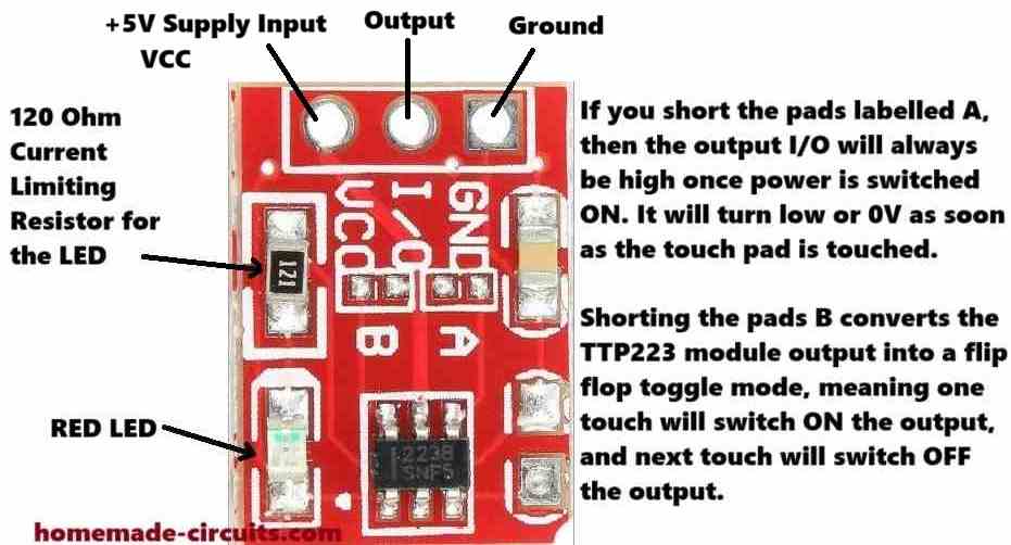
So as we can see, we have a ground supply terminal, an output terminal in the middle, and a VCC input terminal on the left side.
The VCC pinout will need a +2.5v to +5V power. The I/O output pin by default will generate a low signal or a 0V signal, until you touch the pad on the other side of the board.
As soon as you touch the pad, or bring your finger close to the pad, the I/O pinout will give you a high signal, which will equal to +5V or the voltage that's supplied on the VCC terminal.
We also see a resistor and an LED soldered on the TTP223 board. This resistor is marked as 121, which means it is a 120 ohm resistor.
The LED is a red LED which is actually quite useful as it quickly lets you know when the I/O output changes state and goes high, in response to a touch on the touch pad.
We can also see pads labelled A, B and another empty pad on the right side without any label.
These serve as additional functionality for the TTP223 module.
So I have explained how these jumper pads can be used to modify the working attributes of the module.
How to Connect A and B Pads
When you join or short the pads labelled A, then the output I/O will always be high once power is switched ON. It will turn low or 0V as soon as the touch pad is touched.
It will stay low as long as the touch pad is in contact with your finger, and will turn high once the touch is removed.
So basically it reverses the default I/O output specification of the module in the opposite direction.
Shorting the pads B converts the TTP223 module output into a flip-flop toggle mode.
Therefore, now when the module is powered and you touch the pad, the output will alternately turn ON and OFF (flip/flop) in response to subsequent touching of the touch pad.
The third jumper pads on the right side without any label can be used to reduce the touch sensitivity of the TTP223 module.
You can try connecting any ceramic capacitor below 5nF across these pads and reduce the sensitivity to some degree.
This means, now the touch pads sensitivity will reduce and will not respond if your finger is at some distance away from the pads.
Use TTP223 with a 12V Relay and 220V Loads
If you want to connect a 12V relay with a TTP223 output, you can configure a relay and the TTP223 module as shown in the following diagram. Using this setup you can easily switch any 220V load ON/OFF with a TTP223 module.
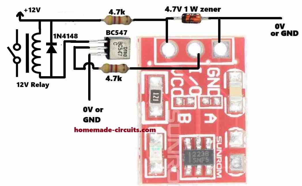
The 12V DC is reduced a 4.7V DC for powering the TTP223 module through a 4.7V zener diode and a 4.7k limiting resistor.
The I/O output is configured with a BC547 transistor which drives a relay on its collector side using the 12V DC.
If you want to use a 5V relay, then you can eliminate the upper 4.7k resistor and the 4.7V zener diode, and connect a +5V supply directly to the relay and the VCC of the TTP223 module.


Questions & Answers
Thank you Swagatam for the updated “How to Use TTP223 Capacitive Touch Switch Module [Pinouts Explained]” article. It has cleared up my confusion.
I bought some of these touch modules and some 5V relay modules to make some switches for toggling household lignts. The relay modules have a red LED to indicate power and a green LED to indicate they have been switched on, however I discovered that the relays I bought engage and their green LEDs illuminate when receiving a LOW signal rather than a high signal.
I tried to compensate for this by closing Jumper A on the touch module, expecting that it would send a high signal when inactive, and when touched its signal would go low and its red LED would light. In other words, I thought closing Jumper A would reverse the normal behaviour of the touch module. It doesn’t. As you have explained, closing Jumper A simply changes the default (initial power on) state to high rather than low.
With Jumper A closed I can use the relay’s NC connection to control my lights effectively, the only drawback being that the LED on the touch module will be illuminated whenever the lights are switched off..
Thanks for all you do to promote electronics knowledge and creativity around the world.
Chuck Cram, Canada
.
Thank you Chuck, Glad you liked the post.
I think the problem is related to your relay module, because the TTP223 LED will switch ON/OFF correctly as per the high/low situation of its OUT pin.
Instead of using a relay module, if you could configure a discrete 5V relay, with diode, transistor etc with the TTP223 module and use external LEDs with the OUT pin of the TTP223 that would illuminate the LED correctly as you want it to be.
Hello, what is the part to the right of jumper A? What is the value of this piece? Thanks
Hi, that could be an SMD capacitor. The value is not known to me, you may have to find it using a capacitance meter.
Hi Swagatam,
I have a circuit that uses a TTP223 with both “A” & “B” open. The output from TTP223 triggers a BC548 that grounds a 555 one shot. The output from the 555 one shot triggers a BC548 that actuates a 5V relay. The relay NO contacts feed 5V and ground to a 5vDC motor. Everything works except the motor draws too much current for the 5v battery supply. The motor is one step up from a 130 motor. The 130 size motors really don’t seem to have enough power for my set up. The circuit draws 370ma with the motor running. I am trying to fit all of this in a small box, so that is why I am using AAA batteries. What do you think about using 3 AA batteries for 4.5v ? Space is the limiting factor. I can power it with a USB cord, but that makes it cumbersome & limited as to where you can set it up.. Lithium batteries are expensive which would make the device less attractive. Any suggestions????
Hi Norman,
AAA batteries will not last long with 370 mA current drain, also remember that the 5V relay will also draw a significant amount of current.
So, an USB supply or a Li-ion battery are the only two viable options available for you.
Hi Swagatam,
I am now powering the referenced circuit with 5v USB. The circuit works as long as I am touching the TTP223. It appears that the one shot is not timing as expected. I have tried increasing the capacitor(smd) from 10Uf to 22Uf to 47Uf with no change. The timing resistor is 100K. It makes me think that the motor current draw is affecting the 555 one shot. I can email you a schematic if you need more information. Thanks!!
Hi Norman,
I saw the diagram which you sent to my email ID.
The problem might not be due to high current consumption by the motor, because the motor current is handled by the relay.
The problem could be due to the high voltage spikes generated by the motor.
Please connect a reverse diode across the motor wires along with a 10uF capacitor.
Additionally add a 0.1uF, and 100uF capacitors right across the IC 555 supply pins, along with a 1N4148 parallel diode.
Let me know if that helps.
Hi Swagatam,
Thanks for the quick response. Your solution works perfectly. You are such a good resource for DIY electronic enthusiast. Thanks again for being there when we are struggling.
Thank you Norman, I am glad I could help you to solve the problem.
All the best to you!
is there no contact dendring ..pulsating like a normal switch does from going one state to an other..i would like to know if its just ONE pulse…or more
..
Sorry, I did not understand what you meant by contact dendering?
Do you mean flip-flop? or alternate ON/OFF mode.
normal switch which is switched on goes not direct on ..but goes on of on off until the contact comes to a solid on state .
does this item get no issues like the switch and just creates one steady pulse ..
It can be turned into an ON/OFF switch by shorting the pad B.
hi swagatam.
re your post……” Use TTP223 with a 12V Relay and 220V Loads”
https://www.homemade-circuits.com/ttp223-capacitive-touch-module-explained/
what value components would i use for 9v operation ? please
thank you, dave
Hi Dave, you just have to replace the 12V relay with a 9V relay, that’s all, nothing else needs to be changed.
Hi Swagatam,
I have a circuit that uses the TTP223 with a 34838 IR receiver module that simulates a touch by sending a negative signal through a 1M resistor to pin 3 of TTP223 when it receives a 38khz signal from the IR transmitter. This makes a very nice toggle switch. I have used this setup many times with success. I am using this to switch an LED on and off using a NPN transistor, which works fine when a standard LED is used. My problem is I want to use self-flashing LEDs. I switch the circuit on and the LED flashes through it’s cycle and then it turns off the TTP223. I know this should work as a remote control toggle switch. I just don’t understand why the self flashing led would trigger the TTP223 as if it were touched. Help!!!
Hi Norman,
Without checking the circuit practically it is difficult for me to suggest exactly why the self-flashing LED may be triggering the TTP223 module. One possible reason could be some kind of RF noise from the LED that may be rattling the TTP223 to get triggered. You can try adding a 1k series resistor with the TTP223 (+)supply and also capacitors across the supply +/- terminals of the IC and see if that solves the issue or not?
Hi Swagatam,
I tried your suggestion. First I added a 10uF cap and a 0.1uF cap to the supply of the circuit. No change. I then added a 1K resistor to the supply to the TTP223. The circuit turned on but would not turn off with the 38khz transmitter. After checking the circuit, I realized I had the 1K resistor in the supply to both the 34838 and the TTP223. I fixed that and tried the circuit again. It turns on with the 38khz transmitter but will not turn off with the 38khz transmitter. It will turn off when I physically touch the TTP223. Any other suggestions? Thanks!
Hi Norman,
I saw your schematic in my email, it looks like the LED anode must be directly connected to the +5V supply through a 1k resistor, and not to the VCC of the TTP223.
Ans also the 1uF between the sensing input of TTP223 and ground must be removed.
Hi Swagatam,
I just posted and made a mistake in saying the circuit would not turn off with the 38khz transmitter. The problem is the circuit still turns itself off when the flashing LED finishes it’s first cycle. So the changes did not help or hurt the circuit. Sorry for not being clear with my description.
Hi Swagatam,
I found a solution. I used my original circuit and added a 1n4148 from the output of the TTP223 to the 10K resistor at the base of the BC337 transistor which provides a ground for the self-flashing LED. Thanks!
Thanks Norman,
Glad the problem is solved now.
Hi Swagatam,
I spoke too soon! The circuit works perfectly on the bread board but does not work correctly on the PCB. When I press the 38khz transmitter the circuit turns on and the flashing LED flashes through one cycle, then it turns off. I thought that maybe the electrical traces running under the touch switch might be the problem, so I reoriented the circuit to prevent any interference with the touch switch. No change. I tried touching the TTP223 and the circuit worked as planned. So, if I physically touch the TTP223, the circuit turns on and continues until I press the 38khz transmitter or touch the TTP223. So, the circuit works correctly with a physical touch of the TTP223 but turns itself off if the IR remote turns it on.????
Hi Norman,
did you implement the corrections which I had suggested in my earlier comment?
“…..the LED anode must be directly connected to the +5V supply through a 1k resistor, and not to the VCC of the TTP223.
Ans also the 1uF between the sensing input of TTP223 and ground must be removed…….”
Yes, I supply the TTP223 through a 1k resistor and supply the LED through a 1k resistor directly from the 5v supply. No change. Why would the circuit work correctly if I physically touch the TTP223 and not work correctly when it is turned on with the 34838 38khz remote control?
We have to check whether the remote control output is generating the required ON/OFF logic correctly or not, or we may have to use a transistor buffer between its output and pin#3 of TTP223.
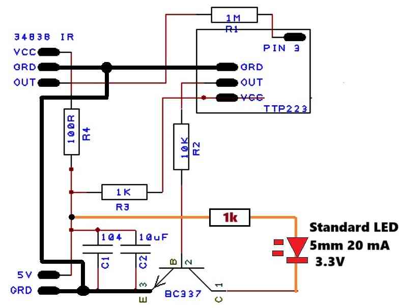
For the moment you can try replacing the flashing LED with any ordinary 3.3V 20 mA LED and check the response again, and make sure to connect all the ground lines in common as shown in the following image:
I do not know how to use or make a transistor buffer. The circuit is working the same on the breadboard and PCB now. If I touch the TTP223, the circuit works correctly as originally designed. That is: 34838 output grounds pin 3 of TTP223. TTP223 is powered by 5v through a 1k resistor. TTP223 output triggers a BC 337 transistor through a 10k resistor to the transistor base. The BC337 grounds the LED from its collector to emitter. If I turn the circuit on with the IR remote transmitter, the circuit times out after 7.5 seconds. If I turn the circuit on with the IR remote transmitter and then remove the connection from the out pin of the 34838 to pin 3 through a 1m resistor, then the circuit works correctly. Therefor the 34838 is creating the problem. I tried two different IR remotes.
Ok, please try the following buffer circuit and check if it works or not:
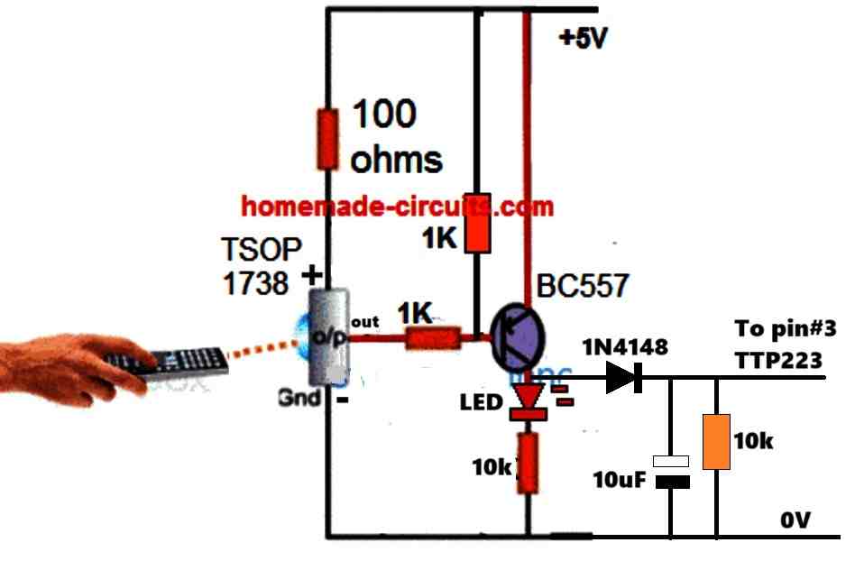
Hi Swagatam, Ok, I set up the buffer exactly like your schematic on the bread board. The circuit powers up but times out in about 9.5 seconds. I tried two different TTP223 units. No Change. I really appreciate your efforts! I guess I will use a 4017 circuit in place of the TTP223 to achieve the toggle switch. I don’t want to keep beating a dead horse! Thanks!
Thanks Norman, what happens if you toggle the pin#3 with +5V through an push-switch manually, with a 10k resistor connected between pin#3 and ground?
It would be interesting to know what is causing the timeout?
The 4017 option could be used ultimately to solve the issue, afterwards…
Hi Swagatam, Connected a 10 K resistor to pin 3 of TTP223 and the other end of resistor to ground. Connected VCC of TTP223 to +5v and ground pin of TTP223 to ground. Momentary +5v to pin 3 of TTP223. Nothing happens. Momentary +5v to ground side of 10K resistor. Nothing happens.
Thanks Norman,
Then how do we use the pin#3 to manually toggle the IC output? If it is not working through a manual option, then how can be expect it to work through an external source?
So finally it seems it is better to go for the 4017 option.
Please give calculations of base resistor of 4.7k and also of power supply rail resistor of 4.7k
Transistor base resistor can be calculated as explained in the following article:
https://www.homemade-circuits.com/how-to-make-relay-driver-stage-in/
The zener diode resistor is not critical and can be any value between 1k and 4.7k. More details are given in the following article:
https://www.homemade-circuits.com/how-to-calculate-zener-diode-resistor/
hello sir I hope your remember our lm358 temprature control circuitry with lm35 temprature and also with ttp223 touch module which was connected to the bc546 but now when I replaced the old ttp223 with the new one it’s became a nightmare for me its responses because worst now it like if I touch my fingers to its surface then it’s starts the circuit but after few seconds it’s led blinks madly don’t know why and also if the desired temperature have been reached this ttp223 won’t let the circuit turned off because of its blinking and also I have tried several ttp223 all of them have the same responses why ? I have connected 1k in series to the bc546 and i/o pin and the supply voltage for the touch module if 5.4 v sir please help pura circuit ho gaya tha but ye touch module ne sab bigad diya please help
Hi Neeraj,
Yes I remember…
Did you check the two circuits separately?
Please check the working of the two circuits separately and check their responses, and then join them carefully and check again at what point the touch switch stops responding?
there’s only one circuit sir !!! not two ! and can I have simple circuit to check the ttp223 ?
One circuit is your temperature controller circuit, the other one is the TTP223 circuit…so you circuit which you must confirm separately first.
The TTP223 is a simple circuit itself, what is difficult in it?
sir it’s weird some of the touch module was faulty but some of them were in a good shape and worked perfectly but the catch is they are working perfectly only on 24v input at the temperature circuit and if I use 48v which is required for the heater this touch module won’t work at all I don’t know why ?! in 48v modules reaction was like automatically on and off all the time even if you won’t touch it !!! how can I solve it ????
Neeraj, the TTP223 are designed to work with 5V DC and so you must step down the 48V to 5V. Maybe this is the main issue why your TTP is not working correctly.
For converting the 48V to 5V you can try the following circuit:
https://www.homemade-circuits.com/adjustable-1-2v-to100v-dc-buck-converter-circuit-using-lm5164/
and when this blinking was happening the voltage between vcc to gnd was 3.8v and vcc to i/o was 2.6 to 2.8 v ! and it’s blinking all the time !
and if I check voltage without ttp223 at the vcc and gnd its 5.3 and at i/o and gnd its 0.7v and if I connect multimeters red wire with the i/o and gnd its stars and it won’t turned off until I remove the red wire from the i/o pin !!!
No need to check the voltages, just check the working of the circuit with a load. You can provide me the link of the circuit diagram which you ae using I will try to suggest.
sir as you said how to connect led and check ttp223 can you tell me again! because your previous comments is not visible in lm35 temprature control blog ! sorry!
Neeraj,
The comments might take 4 hours to become visible… due to caching, sorry about that.
Connect LED anode to OUT of the TTP223, cathode to 1k resistor, and resistor end to ground. Now check the response by touching the touch pads.
no no sir you are getting it wrong it’s getting 5v or some but in 24v it’s working perfectly but in 48v it’s not ! in both cases we have 5v for the ttp223 module with the help of 5v zener diode and 10k resistor which is directly connected to the 48v or 24 v positive line ! and as you can see 10k is connected to the i/o to the bc546 is changed with the 1k and at the vcc we have changed 1k to the 10k and connected to the 48v or 24v directly so this helps to step down 5v for the ttp223 module ! we don’t need external module for it ! right now we are facing issue which is nonsense to me like we are getting same voltage and all the things in 48v version but it’s not responding as it was doing it with 24v . !!!!!
Neeraj,
I think the 10k resistor is limiting too much current to the TTP223 module, and that is why it might not be working correctly.
Please try powering it separately from a USB 5V and check the response.
good morning sir as you said to use 5v i did but still the same issue at the 5v with the phone adaptor ttp223 worked perfectly but then I connected the i/o pin to the circuits i/o it didn’t worked at all I don’t know why ! and then I tried some experiments like i replaced directly connected 10k to the 4.7k and then I also replaced 1k which was connected to the base of the bc546 to the 4.7 and now it’s working but not perfectly at all some of the modules works but most of them fails and the issue with the self switch on is not resolved at all whenever I turn on the circuit the ttp223 on automatically!!
Good morning Neeraj, It is difficult for me to troubleshoot your TTP223 problem because I cannot test it myself, and also because you are using a 48V as the supply.
If you are using a separate 5V for the TTP223 module and still the circuit is having problems with the temperature controller circuit, then it is difficult to judge the issue without a practical checking.
You can try using an opto coupler between the TTP223 output and the base of BC546 a check the results, or simply quit the TTP and create a CMOS IC based touch switch circuit.
and somehow it’s starts working with the 48v after the desired temperature reaches the temperature circuits turns off and the this happens like it’s switchs rapidly automatically without any touch until its on again
and if I use 10k at the vcc and 4.7k at the base of the bc546 then this module works 80 percent good but still automatically on is a problem
automatic ON is happening without TTP223 connected or with TTP223 connected??
actually yeah I think we are exeding it’s voltage level because we are giving it 5.4 v and idk how much amps ! and also it’s maximum limit is 5.5v ! and also there might be some issue with the bc546 resistance value which is connected to the i/o pin ! in my opinion we can reduce voltage by changing 10k and 5v zener diode and to change its madly behaviour we can implant some between i/o and bc546 or as you said earlier change the whole stuff !
You can try reducing the supply 10k resistor to 4.7k or 2.2k 2 watt and also make sure to connect 100uF capacitor across the zener diode…it should do the trick…
there’s no other easy option than TTP223 in my opinion…
automatic on is happening with ttp223 and what’s the cmos !?
who can I enable it ? what’s the circuit
specifications?
Then the problem is with the TTP223, it is not stable with 48V supply step down.
CMOS ICs are ICs which begin with 40xx for example 4017 IC:
but these circuits also work with 12V only.
Keep trying with TTP223, connect a 100uF across its +/- supply inputs or the 4.7V zener diode and check the response.
sir nothing changed same as before! actually to clear all the doubts I have separately made a circuit with 5v zener and 4.7k resistor and capacitor and connected it with the 48v directly and i/o pin to the. bc546 base with the 4.7k resistor but this was same as before same issues!!!! can we make something which can literally reduce voltage and make it more stable and easy to switch? we only need a fraction of the voltage just to start the temperature module it’s working even with the touch of the finger to bc546 base !
Neeraj, to reduce voltage efficiently, buck converter is the only option, there’s no other easy way…
Did you check your circuit with 5V from an external power supply, without using the 4.7k and zener…is it working??
sir I have seen youtube videos that you can also add bc547 transistor to make it more stable ! is that true ? and if we connect it’s output pin directly to the bc546 base then ? or we can connect bd140 transistor also for switching if bc546 won’t work?
Neeraj, We already have the BC546 in your design so where will you add another BC547?
If you the output directly to BC546 base, the BC546 will burn due to absence of current limiting…
BD140 is already configured with the B546 in your design…
did you test TTP223 response with an external 5V supply after configuring it with your 48V system?
sir I have tried external 5v supply and the results were like this !
* after connecting i/o pin with the series of 10k resistor to the bc546 touch module stayed on and it won’t let the circuit turned off after some minutes later the touch module led turned off but still it won’t let temprature control circuitry off and the range of capacitive have increased automatically so much and some times this touch module turned on automatically and off automatically! i also have connected 100uf capacitor to the ground and vcc of the ttp223 but still issue remains unsolved
OK, in that case we can try an external BC547 configured between the 10k end and the BC546 base. But now the ON/OFF touch response will become opposite, which I think is not an issue.
Connect the 10k end to the base of the BC547, emitter of BC547 to the common ground of the 48V system and the TTP223 board, and the BC547 collector to the base of the BC546….now check the response…
I hope you have connected the grounds of the TTP223 and the temperature controller board together in common…which is a must..
nope sir it didn’t worked at all the ttp223 behaviour is same as before and now it’s not been able to switch bc546 ! I have a idea can we get rid of this ttp 223 ? because whenever I touch bc546 base with the twizzers it’s stars and also if I only connects i/o pin of this ttp223 and touch it this works and switches the bc546 even if I don’t connect vcc and ground of it !
Neeraj, sorry, it should be actually BC557 and not BC547. Pleas connect the 10k end to the base of the BC557, emitter to the +48V supply and collector to base of BC546 through another 10k resistor. But BC557 cannot handle 48V so I think you should use some other PNP BJT with this configuration rated at over 48V…
If you think just by touching the BC546 base you can switch ON your controller, then you can try that…we had earlier already discussed about this method before but due to some reasons you changed the decision and decided to use TTP223.
and also sir if I check voltage at vcc and gnd only if I connect i/o pin to the bc546 with series of 10k resistor I got 1.3 v ! remember I have not given any voltage to the ttp223 and only connected it’s i/o pin and this works but only if I touch it’s pads
That is completely wrong method and should not be tried…
can I use tip122 transistor because this have 100v and 5amp capacity !? if yeah then how to connect it !?
Actually it should be PNP BJT, but you can also try with TIP122 which is NPN….also because TIP122 is too big, you can replace it with some other smaller 100V BJT afterwards.
Connect collector to the +48V supply, base to the 10k from TTP223, emitter to the base of BC546 through a 1k resistor…
sir can we use bd140 because it’s a pnp bjt with the 80v capabilities if yeah then tell me the connections !
First try with TIP122 and check the results as explained in my previous comment, then next we can try BD140..
nope nothing worked same as before i have tried every scenario and the effects are same as before now I’ve decided to get rid of this touch module and go for metal which will be directly connected to the base for bc546 ! do I need any resistor between metal and base of bc546 ?
The BJT method which I had suggested is 100% correct, but not sure why it is not working for you…Whenever something looks doubtful, always verify it by connecting a series LED.
You can try the metal plate with the base of BC546 but it can give false triggering due to noise interference in the atmosphere.
Make sure to connect a 0.1uF capacitor between the BC546 base and ground. You can add a small value resistor, like between 10 ohm and 30 ohm in series with the plate connection…
sir I think I have seen a pattern of i connect this TTP223 module with the 5 v supply and also with led in series and if I carry it closer to the temperature circuit then mysteriously it’s turnd on almost 7cm far how ? i have not connected it’s connection to the temperature circuit but still it’s turns on !???! and also if I take it to the closer to the SMPS !
Neeraj, please connect a capacitor between the base/emitter of BC546 in your temperature controller circuit and now check the response again, the automatic switch ON should stop happening.
sir there might be mistaken in my previous comment ! it’s 24.7k at the vcc which have connected directly to the 48v and at the i/o and base of the bc546 it’s 4.7 k !
Neeraj, that’s great, glad it is somehow working now. Did you connect the 4.7V zener diode also?
yes sir i have connected zener diode but i have a question right now I have connected several resistor to make it 24.7k and now I wanna use only one resistor in vcc should I go for 25k ? resistor?
Sure, the combined resistor value can be made into a single resistor. You can start with a 22k resistor first and then increase it slowly until you find the most optimal one.