In this article I have explained a simple temperature controlled relay circuit which can be switched ON/OFF depending on the temperature on its temperature sensor.
Meaning, when the temperature on its temperature sensor rises above a set threshold point, the relay switches ON, and when the temperature drops below the threshold, the relay switches OFF.
Any load connected across the relay contacts thus also switches ON/OFF depending on the temperature level of the sensor.
Using a Thermistor
Clearly for this temperature switch relay circuit to work we require some sort of electronic sensor whose characteristics change with temperature.
You will find a couple of primary types of components that exhibit ideal temperature sensing qualities: semiconductor junctions and thermistors.
For this circuit we have decided to work with a thermistor.
Thermistors are exclusive varieties of resistors constructed from heavy metal oxides and built to possess highly varying "resistance versus temperature" properties.
Circuit Description
The following figure exhibits our simple temperature controlled relay switch circuit, which even with its ease-of-use has the ability of providing precise and dependable results over an extensive range of temperatures.
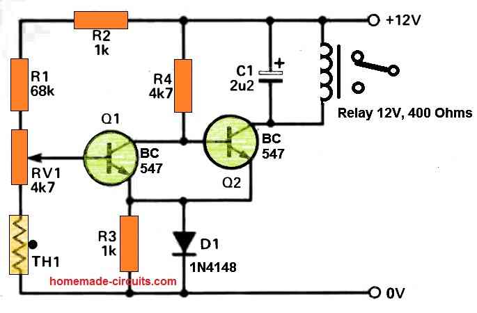
The preset, RV1 enables the working temperature to be established, and is tweaked to make sure that below the preferred cut-off point, the voltage across base of Q2 is adequate to allow it to be in the switched on condition.
As the thermistor temperature increases, the voltage around the base of Q1, which is extracted from the resistive divider network comprising of R1,R2, RV1 and TH1, starts falling, ultimately permitting Q1 to turn off.
The moment Q1 turns off the voltage around the base of Q2 goes up and the relay is switched on.
The diode, D1 delivers temperature compensation to the a pair of transistors, and C1 functions like a back EMF preventer for the relay. As indicated in the diagram, the circuit temperature range could be anywhere around 35 to 100 degrees centigrade.
As long as the relay is in an inactive condition, the current draw of the circuit is very little at around 2 to 3mA. Therefore, the circuit could be powered from either battery packs,or a tiny DC power sources.
Construction
A straightforward circuit which is explained here might be constructed over a tiny PCB. When constructed, the circuit must be two times inspected for proper positioning of diodes, transistors and capacitors, and only after that should be powered ON.
The thermistors possess no built-in polarity, and could therefore be hooked up without worrying about its direction.
How to Set Up
To set up the circuit, adjust the preset RV1 to roughly at the midway, and then slightly heat up the thermistor using some sort of external heating source, for example you can take a light bulb, or a soldering iron in close proximity to the thermistor.
Within a few seconds you should find the the relay clicking ON and any kind of device connected to the relay contacts could be seen switched on.
Next, as soon as the heat source moved away from the thermistor, the thermistor will start cooling down, until its temperature decreases below the trip-point and the relay switches OFF, turning off the connected load.
Applications
The relay output of this temperature controlled relay circuit could be attached to either an alarm device, or any kind of heating system, or cooling system.
For example the circuit could be used for switching ON a cooling fan as soon as the temperature is detected to be beyond a high threshold.
It could used for cooling heatsinks or for cooling semiconductor devices in inverters.
While picking out a appropriate location for the temperature sensor, be cautious to stay away from putting it in a situation where it will likely be exposed to external heating agents.


Questions & Answers
Thanks for the good work.
Please how can this circuit diagram be adjusted to activate the relay at 37.8°C and deactivate it at 37.6°C?
Thanks in anticipation.
It is not possible to get such sharp accuracy from this design.
You might need to modify one of the following circuits, for getting that much accuracy:
https://www.homemade-circuits.com/making-simplest-room-thermometer/
Thanks Swag.
I checked the link you suggested (https://www.homemade-circuits.com/making-simplest-room-thermometer/) and found thermometer projects, but the one I am requesting for should be a thermostat project instead since it switches the relay on and off at different temperatures.
Please, if you can help, I will be very grateful Sir.
Hi Lisbon,
“….activate the relay at 37.8°C and deactivate it at 37.6°C”
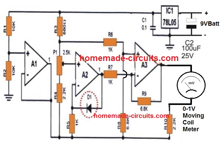
These are not two different temperatures, they are almost the same, with a difference of just 0.2 °C, this can be achieved only through an IC based temperature sensor and an opamp based driver.
If you add a relay to one of the thermometer projects then it will do the job exactly as you have specified.
Please build and this design and let me know, then we can add a relay to it afterwards.
Explanation is given in the thermometer article.
Hi. I can solder up a circuit but not able to design one effectively.
I have a 12V/3A water pump that I am going to use to circulate water from a diy heat panel on the roof to the hws under house. I want to use a supercapacitor to do the heavy lifting driven from a 36V solar panel with a buck converter on it. I want to use a relay that would switch the capacitor ON for the pump when the voltage is, say, 15V and then switch OFF if the voltage drops below, say, 9V. I don’t want to burn the pump motor out with under voltage during dim light hours.
i am guessing that the circuit would be simple but is beyond me. Thank you, in advance. Vic.
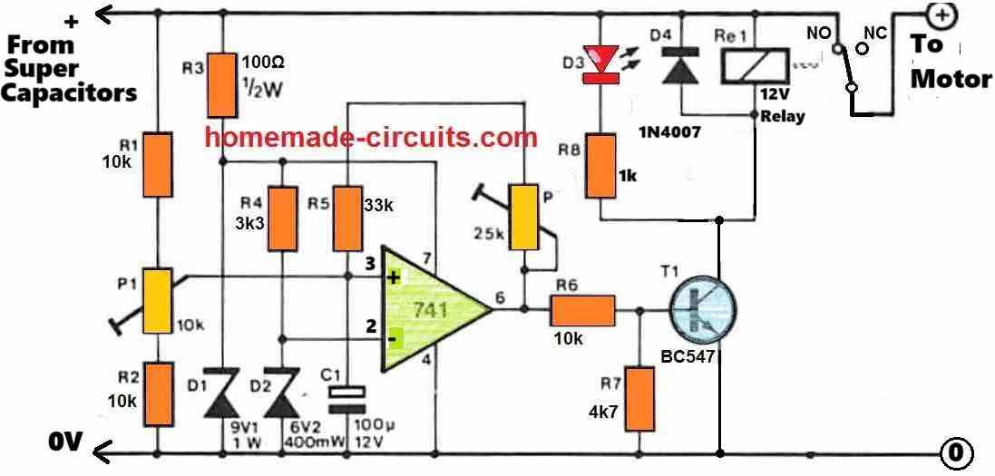
I have designed the required circuit, you can view it under the following link. If you have any further questions please feel free to ask.
Swagatam
What a great service you provide! The work you do isn’t work. It is best very best form of play. It must give you great pleasure to use your brilliance to provide solutions to the many problems people have.
Thank you very much.
I will begin gathering components and solder it up. I will let you know how it goes.
One question. Are D1 and D2 special types of diodes?
Victor
You are most welcome Victor,
D1, D2 are standard zener diodes.
P1 and P2 are presets or trimpots. P2 is connected with pin#6 of the IC.
P1 and P2 can be set in the following manner:
Keep P2 disconnected initially.
Rotate the slider arm of the P1 preset completely towards ground or R2.
Feed 14V or 15V DC from the super-capacitor side. Now, slowly adjust the P1 preset until the relay just clicks ON (D3 is illuminated). If you have problems, try removing R2 and replace it with a short.
Next, connect P2 back and adjust its slider so that its resistance becomes minimum or 0.
Now reduce the 15V DC down to 9V, and adjust P2 again so that the relay just turns OFF (D3 shuts off).
P1, P2 setting may interact with each slightly so you may have to tweak the setting a few times until the right balance is achieved.
The setting up is now complete.
Hi Swagatam
We have had some fine weather so have been in the paddock working. Today was showers so I decided to have some fun with the cct. I played with it in stages so that I could try to understand how it all works and mostly OK. For testing, I am using a 13V battery with a buck as my variable supply and set the upper limit to 12V and lower at 9. Once ON at 12, I slide it down to 9 and it switches OFF – as it should. However, it will not turn on again when I slide it back up to 12+. It only switches on again if I briefly remove the feedback loop and reinsert it and then the cycle repeats. Removing the capacitor had no effect. Any ideas? I will keep playing with it tomorrow as showers again predicted.
Have a great day.
Vic
Thanks Victor,
Yes, the P1, and P2 settings will interact with each other a bit, and therefore the hysteresis will need some extra effort in order to make the cut-offs accurate.
You can do one thing, reduce the R5 33k to 1k and replace the P2 preset with a 100k preset of a 220k preset, this will allow you to get wider range of adjustment for the hysteresis control.
Have a nice weekend.
Hi, I can help you with the circuit design, however there are some confusions.
How is the super capacitor connected with the buck converter output? Are they connected directly with the output of the buck converter or through a relay? And where is the motor supply connected? Once the power is cut off at 9V, the motor should not be switched ON until 15V is reached, is that correct??
According to my understanding, it should be like this: Solar panel output connected to a buck converter, buck converter output connected to the super capacitors, this buck/super-capacitor output supply connected to an opamp circuit for detecting the low voltage at 9V which activates a relay for powering or turning off the motor.
Hello sir I hope you are healthy and well ☺️
Actually I have a issue with is this because sometimes when I use this circuit that you have made for me is getting off without reaching the targeted temperature and some times it’s works fine but at another time after reaching targeted temperature it don’t off ! Relay don’t even switch why ?
Did you understood my point ☝️
Hello Neeraj,
We have already made too many modification in your circuit so it can be difficult for me to understand the issue without practically checking your circuit.
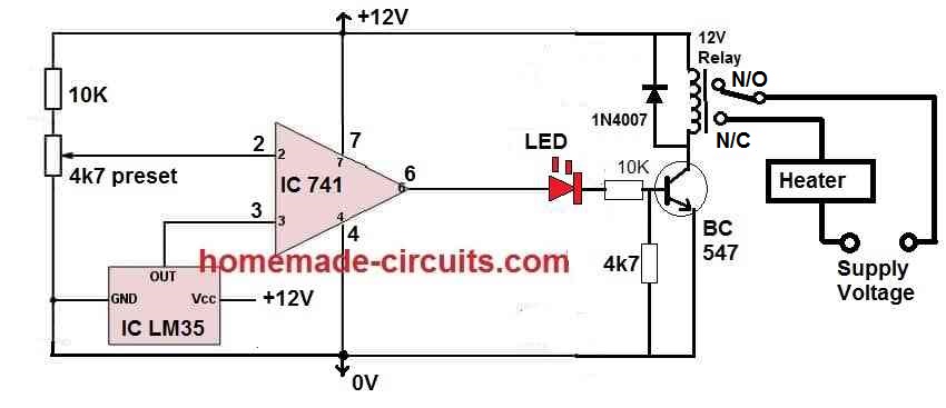
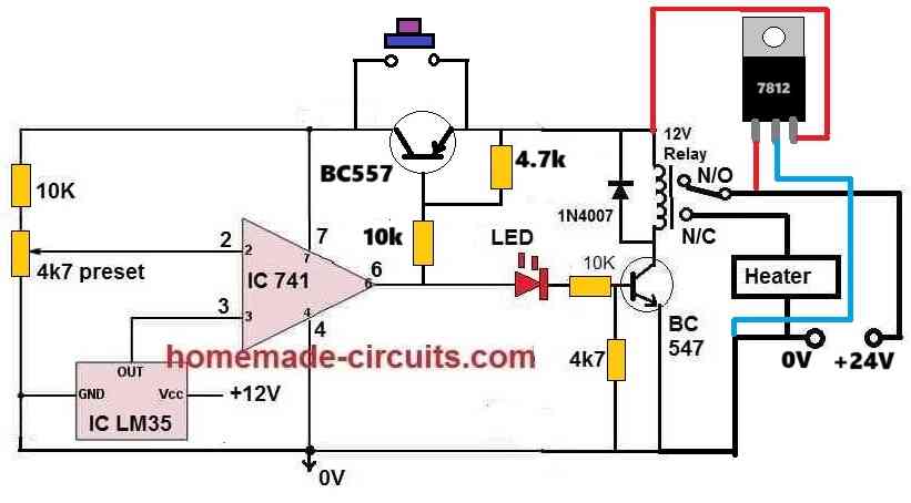
Moreover, thermistors are not so accurate, so if you want more accuracy then you may have too employ an opamp circuit with LM35 IC.
Hey why you didn’t give me earlier! It’s beautiful but how can I add Lm7812 ic?
And what about its efficiency and accuracy?
You can add the 7812 between the +12v input supply and the positive line of the circuit. Meaning, the input of the 7812 will connect with the +12v DC, output of the 7812 will connect with the positive of the circuit, 7812 ground will connect with the ground line of the circuit.
I have a doubt ? I can see the relays connections are wrong! And the input voltage is 24v 15a 360w ! And where is the push button function ? And it will work like the previous circuit? After pressing the push button it will on and after reaching the desired temperature it will cut-off the power !
These are my Little doubts !
You can change relay/heater connections as per your requirement, just check whether the circuit is responding accurately or not.
Sir you are the genius person why don’t you change it ! It gonna make me confused and again I will come back to you again I know it’s a bit quacky! Sorry
What’s about other stuff like push button function and cut off functions ?
Neeraj, You can try the following design:
Okay sir ? i will update you as soon as possible ☺️
OK!!
Sir I got the problem! The 7812 is heating madly and push button function is not working and whole circuit is not working! I double checked everything every connection but still got this issue!
Neeraj,
It will surely work if you do it with proper understanding and in a step by step manner. The setting up procedure is important.
I will update the whole procedure in another article and I will let you know soon.
However, the 7812 heating cannot be eliminated. Therefore i would recommend you to use a 24V relay instead, which will allow the circuit to work directly from 24V DC source without the 7812.
Sir I will try to make it again with proper way and elimination of the 7812 is not needed because 24v relays are so heavy ! I will make this again with proper way ? thanks
Neeraj, 24V relay is not heavy, I would recommend using 24v relay only so that the circuit becomes very simple.
Please do not make the previous circuit, I will make it smaller, so you can try the new modified circuit.
Okay master I will wait for it
I have published it in the following link, you can check it out and if you have questions you can comment under this article.
https://www.homemade-circuits.com/lm35-ic-temperature-controller-circuit-with-push-button/
It will be highly accurate.
Hello sir btw first off all happy new year and I have a problem for you ! So I have tried 5v for the touch module but the whole circuit didn’t worked the temperature sensing function is not working and the touch module also it’s got straight on when connected to the power !
Hello Neeraj,
Happy New Year to you!
I hope you have correctly integrated the following two circuits as per the given suggestions.
Firstly, are two circuits working normally when they are not integrated with each other.
Is the capacitive switch module working OK with the 4.7V zener, 4.7k resistor, from 24V DC input, without the BC557 connection?
Please confirm these.
I have checked then when I connect them to each other and it’s works finely no issues but after that I bought lm7805 and added to the main temperature circuit in the circuit was working but the functions were not quite good after that I connect capacitive touch module with direct bc557 and it didn’t work as it should be ! Thats my issue your capacitive circuit worked super efficiently!
Then don’t use 7805, use 7812 for the temperature sensor circuit…
But I don’t wanna use another circuit for capacitive touch module ! Isn’t there any other way ! ☹️
You will have to add the extra parts on the ttp223 as shown in the previous linked diagram, there is no other option.
Hello, good morning, first of all, happy new year 2024. I just need this circuit, but on the contrary… I mean, when the temperature rises beyond a certain value, the relay must be disconnected, turned off… Thank you very much. Best regards from Italy ??
Happy New Year to You! I think you can replace R1 with the Thermistor, and replace the existing Thermistor point with a short, then it will do exactly as per your specifications.
Sir I am using ttp223 touch module as push botton but after connecting it went to heat up because of the 12v because this models only need 5v thats why I wanted a puch botton to operate this circuit! So for this which transistor should I use ? For this prosess !
Neeraj, is it a flip flop circuit? Meaning, will it produce one touch on, and one touch off?
Sorry’ sir i think I couldn’t define what I what actually I want push botton thats all !
I cannot understand where you want to connect the push button and how you want to configure your touch switch module with the temperature sensor…please explain elaborately.
At bc557 transistor you can see a push botton I want that push botton to be a touch push button not the physical botton just a touch module working as the push button that’s all
Because this circuit board will be behind of the wall of the card board and I don’t wanna hole in it that’s why I want touch module !
Will there be a gap between the hand and the touch switch, or can there be a direct contact with hand?
3mm wall of the gap of the card board ! Between touch module and finger !
TTP223 requires direct touch, it is not capacitive, meaning there cannot be a gap between the touch pad and the finger
OK, I watched a related video, which shows TTP223 can also be used as a capacitive switch, with a gap between the finger and the touch pad..
I will modify our earlier circuit with this capacitive sensor soon.
Stay tuned.
Thanks sir ! ???????
Neeraj, the following circuit is our temperature controller circuit with push button:
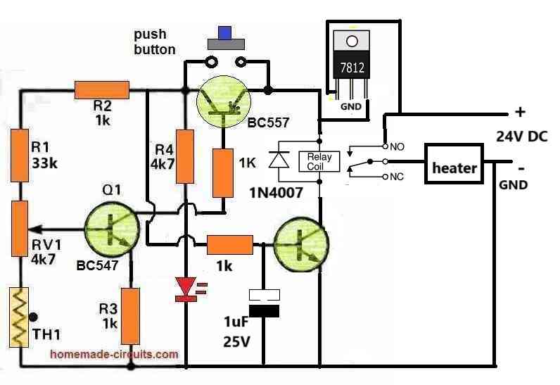
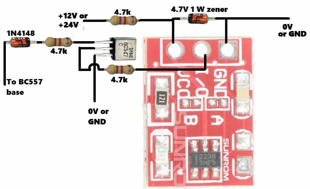
Wire the TTP223 as shown below and integrate it with the above BC557 as indicated.
Sorry to say but i think sir it’s so messy ! Isn’t there any way that only one transistor generate frequency and after getting a little puch it will work as push button?
If you touch bc557 base it will activate and latch…but your requirement is capacitive without physical touching and 3mm gap…not possible without ttp223 and the diagram I suggested.
Okay I will do it but how to connect this circuit with the temperature circuit!
I have shown, +12v or +24v, 0V/GND, and “BC557 base” in the diagram….connect those points in your temperature sensor circuit.
What if , if we add this modules ic and capacitor in our temperature circuit? If yeah then there will much more efficient! Can we ?
If you know which components are used in the TTP223, you can add it accordingly in your temperature sensor design.
I think this circuit diagram of ttp223 can help
You wanted how to configure ttp223 with 24v dc and with the previous temperature sensing circuit for touch less capacitive operations…which I have already given it to you…not sure what is your exact requirement? If a direct touch is workable to you then you can simply touch the base of the bc557 to switch it on.
Sorry i got overexisting look you have designed a remarkable circuit diagram for ttp223 to be used safely for temperature circuit but I am saying that if we use directly ttp223’s components in this temperature circuit as push button without adding much components then I can use it more efficiently! If you understood what I am saying than please consider and if not then leave it thanks ??
You will have to use the ttp223 which is efficiently built…if you try to build it discretely it will create more problems to you and might not work, don’t do it…use the ttp module only as suggested earlier.
Wait a min what if we just lower the voltage of the temperature circuit from 12v to 5v and 5v is more then enough for ttp223 ! Can we do this ? If yeah then it will be more easy to use ttp223 ! I would like to know your thoughts ?
You can check the circuit with 5V whether it works or not? Then you can use 7805 to power the circuit and use a 5V relay to toggle the 24V heater.
By the way getting 5V for TTP223 from 24V is so easy, it can be simply done using a resistor and a zener diode.
I have sanded you the link of the video!
Is it possible to adjust this circuit for a 24v supply voltage? If so, what components would need to be changed?
You can use 10K for R4, and a 24V relay, and use the circuit with a 24V DC input.
C1 voltage must be rated at 40V or above.
Sir i got a new problem in lm7812 this ic is getting shorted i don’t know why I think it’s because the input power is high 24v 15a ! Can we replace is and add a more versatile regulator? That can take upto 360w of the input power ?
Neeraj, the input current to the 7812 does not matter, only the input voltage matters. The input current can be a 1000 amps that will not matter but the input voltage must be below 30v, so 24v is quite ok for a 7812.
I think your 7812 might be duplicate and therefore it is getting shorted, try to get an original piece and check the response….there’s no other option except a transistor regulator…
Sir now everything is working because of my wrong connection relay was not working but now it is at also when load is connected but there’s a serious problem sometimes when I connect the power supply to the circuit the bc557 is not responding as it should and without pushing the button it’s on and working and another problem is that if it’s works fine then after some seconds the relay behaviour is weird it’s switching so fastly leaking volts without pushing the button and after that it’s on operating condition ! I think it’s because bc557 is poor but I have changed it and i got the same thing as before
If it’s confusing then I will sand you the video on the Instagram!
Neeraj, do one thing, in the below shown setup, connect a 1uF capacitor or a 10uF capacitor across the base of Q1 (BC547) and ground line, and check the response. Positive of the capacitor will go to the base.
Sir perfect now it’s perfectly working no current leaking nothing every at it should be but the minimum temperature cutoff range is 200°c it’s High! How to solve this ?
Neeraj,
To optimize the heat range you will have to adjust the preset and/or increase the value of R1 resistor to 68K or more.
One more question sir ! I am using small 5v dc motor at the output before I was using a stepdown modules to do 24v to 5v but it’s a messy kinda so can I use lm7805 at the output to do it ?
You should use 7812, not 7805 because the relay is 12v
Nooo sir I am talking about at the side of the output just as heater at the output because I will also gonna use motor with heater so I am talking about that I was using stepdown module like MP1584 to make 24v to 5v so just for the motor so I am asking that can I use lm7805 at the place of the module ? Just For the motor ??
Ok understood, 7805 can become extremely hot with 24v input, better to use your buck converter instead.
Hello sir how are your ! I have a doubt! I was using 10a 12v relay and as I said you before I am also using heater power rated 360w 24v 15a so it is not affected but that much power why ? (Relay) ?!
Hello Neeraj,
Maybe your relay has a large tolerance margin, so even with a 10 amp rating it is currently handling 15 amp current, but in future your relay contact may slowly get degraded and get damaged.
To increase the temp that triggers the relay would you increase or
decrease the value of RV1 ? I am trying to get it to trigger around
100 to 110 degrees C. Using an NTC 10K thermistor.
Thank You
To increase the temperature range you will have to move the RV1 slider more towards the R1 resistor.
How important is the coil resistance to circuit operation? I am considering using your circuit
to monitor an onboard thermistor on an RGBW high-power LED module. I want it to cut power
to the module if the temp rises to 100 degrees C. There are 2 relays I am considering using. One has a coil resistance of 720 ohms, the other has a coil resistance of 1.2K ohms. Both are 12 VDC.
The coil resistance of the relay is not important as long as it is higher than 200 ohms. Your relays will have no problems with this circuit.
Sir can I add something more to make it more safe and efficient?
Neeraj, The above circuit is safe and efficient, there’s nothing to be added. If you want more efficiency then you will have to use an opamp circuit.
Sir the whole circuit it working perfectly. But I need it to be high temperature cut-off after full turning the potentiometer i can only get cutoff on just 50°c but I need it to be around 80°c or above and also for these high-cutoff did i have to change the value of the potentiometer ?
answer me as soon as possible sir
Neeraj,
You will need to use a different thermistor, with different range.
could you suggest me ? and did i have to change anything in the circuit?
Please don’t use a new thermistor, instead try reducing the R1 68K resistor value to 47K….
Nope sir tried everything changed the MOSFET and everything but the same results! MOSFET is heating up so fast and I am using heater at 24v at starting 15a and at continuous mode will be around 8a but as per the datasheet of the irf540n it can easily take upto 33a and at 100°c 23a !
Confusing ????
Neeraj, I hope you are using the following diagram:
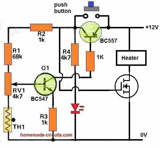
Do one thing, connect a 1K resistor in series with the MOSFET gate, and connect a 10uF/25V capacitor between the gate and source of the MOSFET.
Yeah but with lm7812 regulator ic but could you show me how to connect them all !!!! It’s a bit confusing to me ! Sorry for the problem ???? please!
Whats the polarity of the capacitor and sir i am using 10uf/63v capacitor is it good ?
Sorry, I forgot to add the capacitor at the MOSFET gate, can you add it yourself?
Positive of the capacitor will go to the gate of the MOSFET and the negative of the capacitor will go to the ground line or the source.
Also add a 1K in series with the MOSFET gate. 10uF/63V is fine.
Nothing happened sir same as before after adding capacitor and resistor and now it’s not even sensing temperature!
This problem could be solved months ago but my lazyness killed me ! Sorry for the problem sir !
Now tell me what should I do !
Is there any circuit that will be 100% efficient and effective?
Neeraj,
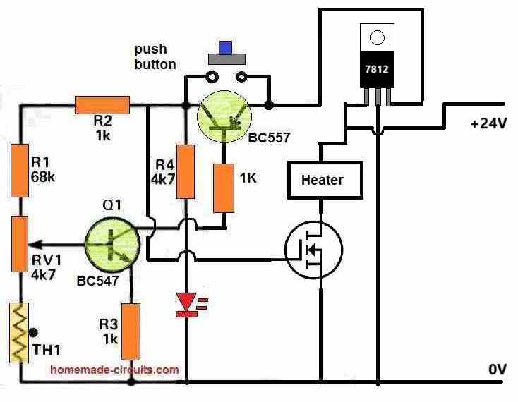
the following circuit which i suggested you is 100% efficient, but the problem is that you are not able to troubleshoot your circuit yourself.
Is the LED illuminating when you press the push button?
Yeah led is working properly and the push button also ! But not the temprature sensing and MOSFET us heating also so rapidly
Remove the MOSFET and the load, check the LED response by heating the thermistor with soldering iron. The LED should shut off quickly due to heat sensing, which would confirm that your thermistor and Q1 are sensing heat.
If the above works that means your MOSFET is faulty.
Neeraj, please check out the diagram below:
nope sir now it’s 60-65 maximum range ! it should have to be around 80 or 90 in order to cutoff at 70 probably! can I change resistance of the r1 ? please suggest me
OK, please reduce R1 to 33K and check….
I have 30k so after testing with it it worked perfectly fine ☺️ thanks sir ! still did i have it continue on the 33k ? sir !
Problem sir after changing resistance and testing it with full voltage the MOSFET was heating madly and it is shorted ! I have changed it and got the same results ! Why ??? !!
Your MOSFET has nothing to do with the R1 resistor. MOSFET can burn either due to overload by the heater or if it is faulty…
did i have to add anything else? sir ?
There’s nothing to add or change in the existing setup, except your 30K resistor.
That’s great Neeraj, no need of 33k, you can continue with 30K, it’s fine.
Ye wala sir
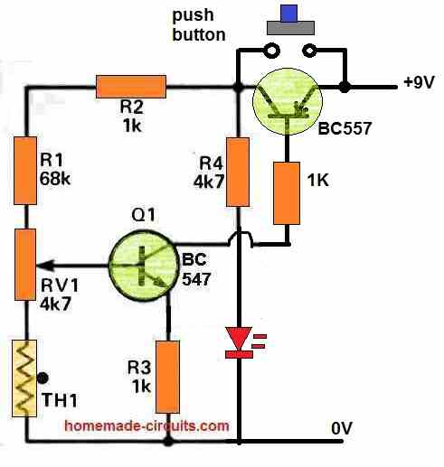
But previously you said it was working perfectly, right?
When you press the button, Q1 must be in the conducting mode, only then Q2 will latch. Adjust RV1 such that Q1 is slightly in the conducting mode while the button is pressed.
sir it happened after applying the heat it went off but the temperature cutoff range is so high because of this I have to turn the pot to the down level!!
That means your temperature sensing is working, but mosfet is not working….so the problem is with the mosfet not with the circuit
You can replace the mosfet with a tip35 transistor and check the response.
TIP35 will also become hot because your load is very high current, so you will have to use a heatsink.
Remember to use a 100 ohm 2 watt resistor in series with the TIP35 base, otherwise it will burn.
The best option is a relay…which will never become hot…
so if the relay is best option then why shouldn’t I go for it !
leave MOSFET how to connect relay because the current at the load will be too high at the starting point it can be around 15a and at the normal state it can be around 8a so i think relay is the most effective!
but a small size relay ! and with it will not much hectic!
Neeraj, I never recommended a mosfet to you, it was your requirement.
For 15 amp current you will need a 20 amp relay which will not be small unfortunately.
but the 15a only will be just for not more then 30sec after that there is a fast decline in amps ! and after a 1 min the constant amps is not more then 8a I have tested all the stuffs ! the whole power to the heater is not more then 360w and it will decrease so faster when the heater will heat up ! so i can I use 30v 10a relay !!!!!!!
If you use 15 amp current on a 10 amp relay contact even for for a second, the relay contacts can get fused or burned.
You can try it and see if that works for you.
sir so which relay should I use ! ?
24v 15a or 30v 20a ?
sir 24v 20a is not available in the market should I go for 16a ?
Neeraj, you don’t need a 24v relay you can use a 12v 20 amp or 16 amp relay…
OK that will do.
sorry sir but there are so many relays in the market and i couldn’t find the right one 6pins or 5 pins or other !? which one should I use ? and how do I connect it in the circuit? where the NC and NO should be connected?
Neeraj, search for 24V, 20 amp spdt 5 pin relay.
Afterwards i will show you how to connect it.
You can use 24V 20 amp relay.
Sir, there is a new problem. The push button function is not working. The module only turns on when I hold down the push button. If I remove my finger, the module turns off
sir I have bought 30v 30a relay with six pin T90 can I work on this for now ? ???
Neeraj,
From where will you get 30V for operating the relay?
Please return it and bring a 12 V 20 amp or 25 amp or 30 amp relay.
The 24V for heater can be configured with the N/C, N/O contacts of the relay.
sir I got the the T74 relay 12v 20a 5pin. Now can you please tell me how to connect it the the circuit board and if it’s a possible then please make a diagram I can understand easily! please ????????
Hi Neeraj, you can try the following updated diagram:
and what about gnd of the 7812 ?
ground will connect with the negative supply line.
and also there in no voltage at the capacitor !
Neeraj, please start a new thread using the comment box below, because all yours comment replies are getting posted randomly and getting very confusing.
nope sir the relay is not working I have checked the relay properly but nothing happened! and after powering up the power supply the bc557 should have to be in off condition until I press the puch button but it’s open without doing it !
any suggestions?
Before connecting the relay stage previously you said that the red LED is switching ON when the push button is pressed, right?? that means the circuit was working before connecting the relay stage?

Please remove the relay stage and confirm again whether the LED is working ON/OFF in response to the push button or not.
Your results are confusing.
sir did i have to use same MOSFET or another one ?
There is no MOSFET in the diagram, the relay driver is a BJT 2N2222…
Neeraj, earlier you said that the circuit was working fine and you were happy with the results and now you are saying it is not working?
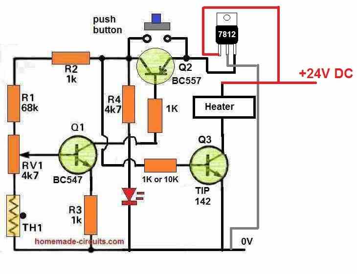
Which circuit are you referring to exactly? Is it the following one:
Sir, will a 100K thermistor work in place of a 10K thermistor.
Neeraj, a 100k THermistor will not work in place of a 10K thermistor.
I am giving my heater a 240W, 24V, 10A power supply, but it seems like the module is gradually stopping. Why is this happening?”
Help sir
Sorry, I cannot solve your heater problem, because the problem may be with your heater which I cannot check.
Sir, I am providing 10 amps of current to this module. Will there be any problem with that?
As long as the voltage is within 24V , 10 amps will not cause any problems.
Sir kya me 78xx ic ko step down module ke tarah use kar sakta hu kya ??
78XX is a voltage step-down IC. Use it as I showed you in the previous diagram.
Wese agar 7812 ic add karna ho to kese kare koi circuit diagram??
You can do it in this way:

There is no problem as such, but the potentiometer needs to be turned down slightly.
OK, then no problems, you can continue with 24V.
Sir The maximum cut-off temperature range
If you change the voltage then the maximum range setting will be altered. Use 24V for the heater, and use a 7812 IC to step down the 24V to 12V, and use this 12V to supply the transistor circuit.
Sir, the module you provided was working perfectly fine, but if I provide high voltage to it, like 24 volts, its maximum temperature increases. However, if I provide 9 volts, its maximum temperature decreases. Why does this happen?”
Neeraj, which maximum temperature are you referring to? The maximum cut-off temperature range or the temperature of the transistors?
Hello sir
I needed some help. MP1584EN is a step-down DC-to-DC module, and I am not able to determine the resistance value of the capacitor in it. Can you help me with this?”
Hello Neeraj,
You can refer to the following article for the complete circuit diagram:
https://www.homemade-circuits.com/ic-mp1584-datasheet-and-circuit-diagram/
hello sir Hume ek temperature control module bana tha jo timer module ke tarah Kam kare jese timer module me hota ha ek baar time set Karo start Karo or wo module siraf uthane time tak hi chalta fir band ho jata par kisi bhi temperature module me esa nahi ha uun me pahale upper limit set karna hoga fir lower limit fir wo kam karta ha par hume sirf ek temperature set karna ha or fir agar hamara module wo temperature reache kar le to bass off ho jaye dubara chalane ke liye hume fir se timer module se tarah start botton dabana hoga ye module hum cold to heat ke liya bana rahe the heater ke liya ke bass ek desired temperature reache karke wo off ho jaye
help sir please
Hello Neeraj, so you want a latching type of temperature controller circuit where the relay will switch OFF and “lock”, and remain locked until power is switched OFF.
You can upgrade the above circuit in the following manner:
can we add a puch to start botton in this circuit diagram and instead of relay can we use MOSFETs ?
sorry push button will not be possible. Yes mosfet is possible…
OK I will try to design that type of circuit tomorrow
sir please puch bottom ko add karna nahi to koi sa bhi botton chalega start karne ke liya
please!
You can try the following circuit:
Sorry, I don’t think this will work. This will turn ON and latch the mosfet when the temperature reaches the limit. Please let me know what type of load do you want to connect on the mosfet?
ek 12v 5amp ka heater
OK, I will try to design it soon.
sir capacitor ko nikal ke bhi dakha kuch nahi huua sab same hi ha koi naya circuit diagram do na jo kam kare please ????
Neeraj, That means your SCR is faulty or your SCR connections are wrong, because SCR will 100% latch with DC trigger.
thank you sir par thoda jaldi karna or aapna UPI bhi mail karna kyuki Hume aapko design ke liya thank you money bhi sand Krna hoga ????
sir iis module me kese pata kare ki highest temperature kitna set huua hai ?
Neeraj, You will have to use a temperature meter to measure the temperature and check at what RV1 preset setting the circuit cuts off or trips.
sir mene kuch derr baad fir try Kiya or ye kam kar gaya
sir agar aap karib hote to me aap ke charan sparsh karta aap ne ek aajnabi ki iitani madad ki uus ke Kiya tahe dill se thank you
sir me wada karta hu ki agar aap ko koi Kam ho mere mutabik to mugha jaroor yaad karna
THANK YOU ????
Thank you Neeraj,
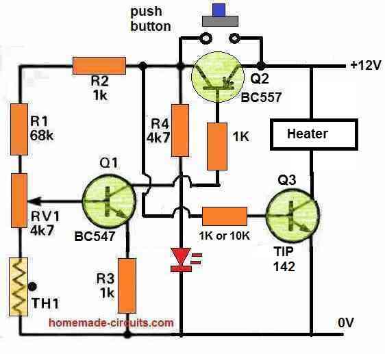
No problem at all, I am always glad to help! I am glad the circuit is working now. For connecting heater just replace the BC547 with TIP142 and replace LED/resistor with Heater wire.
If you have any further questions let me know.
sir koi farak hi nahi pada bjt bhi laga ke try Kiya MOSFET change karke bhi try Kiya par kuch nahi huua! aab kya karu sir
jaha me rahata hu waha se mugha 15-16 km Jana padta ha ye sab parts lene sir koi esa solution batao ki me isse aache se or jaldi se bana lu please ????
Neeraj, did you try the following setup first?
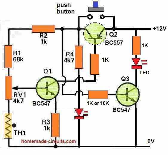
If Q1, Q2 stage is latching perfectly for you then adding Q3 should also work.
When Q1 and Q2 latch, it will activate Q3 also.
When thermistor is heated, the latch will break, Q1, and Q2 will shut off, which will also force Q3 to shut off.
This must work.
sir mene MOSFET ke gate ko resistor se connect Kiya source ko ground se or drain ko heater se par fir bhi MOSFET pure circuit ko direct kar de Raha ha esa kyu ?
This circuit is 100% correct and should work, I don’t know why it is not working for you?

Replace the mosfet with a BJT like BC547 and test with an LED. Make sure to connect a 1K resistor with the base and 1K with the collector LED.
sir MOSFET ke jagah BJT lag sakta hai ? mugha MOSFET suit nahi kar raha BJT kese add kare ?
You can replace the mosfet with BJT. Connect base where mosfet gate is connected, connect emitter to ground, and connect the collector same like drain of the mosfet.
Base must have a series resistor. Try 1K first.
ok sir
You can try the following modification:

sir ye 2 transistor wala circuit bohot aache se Kam kar Raha ha bilkul wese jesa mugha chaiye tha sir aab iis me load kese connect kare ?
So you are saying that the following circuit is working perfectly for you and you want a connect a MOSFET switching with it? I will have to think about it. I will let you know soon:
sir ek problem aa rahi ha mene sub jord Diya circuit diagram ke hisab se par fir bhi
jase hi me module ko power supply se connect karta hu scr wali led on ho jati ha or ager me zener or MOSFET ke connection ko scr ke A Wale pinout se hata ta hu sab theek ho jata ha esa kyu ?
or jo connection heater ke liye nikale the uun me bhi voltage show kar Raha ha Bina heating ke hi
Put a 1N4148 or 1N4007 diode between SCR anode and MOSFET gate and check the results. Make sure you have connected the MOSFET pins correctly. You can also try a BJT instead of a MOSFET to confirm the results. For BJT you an try TIP35
sir me iss module se 24v 10amp ka current pass karunga iis se koi dikkat to nahi hogi na ?
First try with 12V, if it works successfully then try with 24V. Or pass 12V to the circuit, and 24V to mosfet heater separately. Grounds will be common.
sir kaam kar gaya mene power supply change karke dekha to fir scr Kam kar gaya aab batao MOSFET or heater kese add kare ?
OK, so the SCR latch is working now, good. Now connect the MOSFET to the SCR in the following manner:
sir kya hum iis me diode miss kar rahe ha kya ?
where do you want to connect the diode?
sir ek baar aap hi try karke dekha please ???? humra project ruk Raha ha please help Karo
sir mugha laga ki mene circuit hi galat joda hoga par for se naye comments ke sath circuit diagram banaya to wahi answer Mila ek high to temperature par aane ke baad led on to ho jati ha par jase hi normal temperature per thermistor aata ha led of ho jati ha scr bhi change karke dekha fir bhi!
me relay nahi lagana chahta
Neeraj, I have tested many ScR latching circuits and they all have worked for me. You can try the following setup to test whether your SCR is latching or not:
If it does not latch that means your SCR is faulty.
I have designed another transistorized latching circuit for you which you can try:
or sir iis circuit diagram me MOSFET or heater bhi add karna wese me heater ko 24v 10amp ke power se connect karta hu yeh module itna load sah sakat hoga ?
If you are using a relay then MOSFET will not be required.
sir agar relay lagane ne se latch aasan ho jata hai to relay hi laga lenge relay wala circuit diagram bata do
OK, if relay circuit is OK then first make the circuit exactly as ahown in the above article. If your circuit works correctly and operates the relay, then I will show you how use the relay contacts to latch the circuit and to operate the LOAD
sir koi or solution capacitor ko hata kar bhi dekha kuch nahi huua same result koi or circuit diagram hoga ? agar nahi to Iis circuit me MOSFET or heater add kar do !
Without SCR any other circuit will be with 5 transistors with latch, OK?
If you use relay it will very easy to latch….
mene scr ke gate per 1uf 63v ka capacitor lagaya ha iis se to koi dikkat to nahi
1uF ko nikaal de dekho kya hota hai.
Aur LED ka 1K par aur ek 1K parallel mein lagao.
9v wali battery use kar raha hu
9V to theek hai, kaam karna chahiye.
agar yeh kaam nahi kar raha to dusra circuit try karna padega…
sir led on hue thermistor ko heat karne ke baad par jese hi thermistor normal temperature par aaya led off ho gayi ! Sara circuit to sahi Kam Kiya par mugha ye samajh nahi aa raha kyu ek normal temperature per aane par led off ho gayi led ko to permanently on rahana chahiye tha na jab tak me power supply na hatha du
solution sir ?
Neeraj,
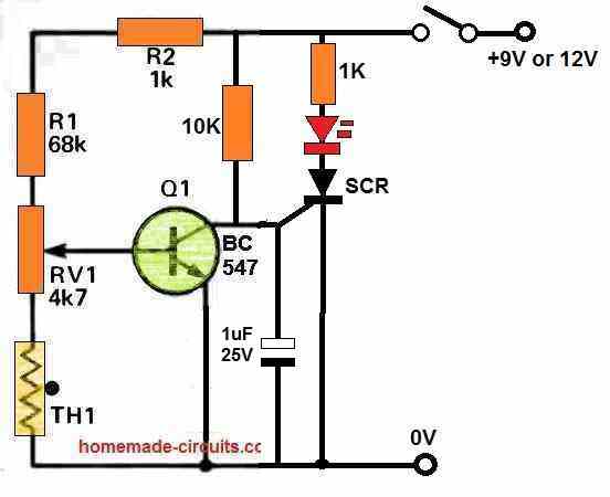
Since an SCR is used it should latch up once triggered. SCR jab DC pe kaam karta hai, gate par positive trigger paate hi LOCK ho jata hai. Tumahare cirucit mein SCR latch kyon nahi ho raha hai samajh mein nahi aaraha.
How much DC voltage did you use?
Try 12V DC.
or kitane voltage ka capacitor?
1uF/25V capacitor. Positive will go to SCR gate and negative will go to ground.
Power supply to circuit can be between 6V to 12V
When power is switch ON, Q1 will be ON, so SCR and LED will e OFF.
When you heat the thermister, Q1 will become OFF, and ScR will trigger ON and lock and LED will be ON
thik hai me capacitor add kar lunga par maaf karna me aap ko pareshan kar Raha hu par iis me load kese connect kare? or SCR ki value Kiya hogi ?
Load will connect with MOSFET, which is not added yet. Please test with LED first, if it works then I will show you how to connect MOSFET with SCR.
SCR can be BT169.
https://media.digikey.com/pdf/Data%20Sheets/NXP%20PDFs/BT169_Series.pdf
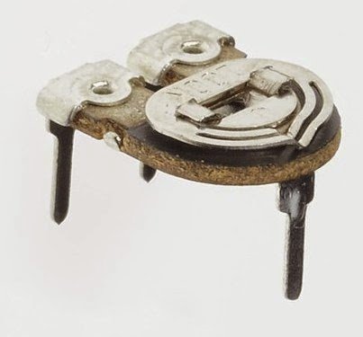
sir circuit diagram me RV1 4k7 kya hai ? (potentiometer) ??
Preset hai:
Neeraj,
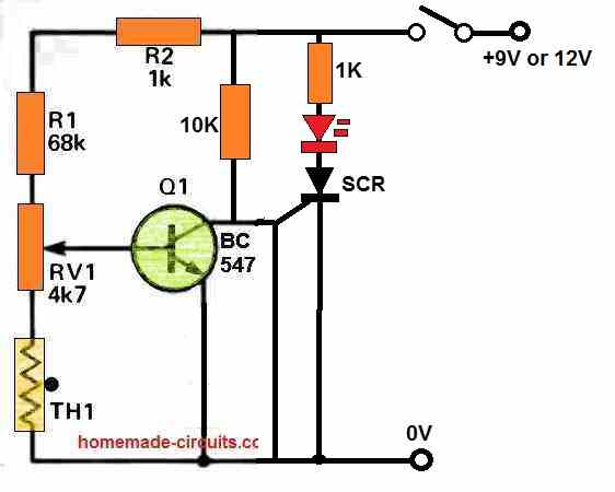
there’s a fault in the following circuit:
The line going down from SCR gate to ground must have a 1uF capacitor in the line.
Please add the capacitor.
Please build and test the following setup. If you are successful then I will show you how to integrate a MOSFET with heater in this circuit, such that the MOSFET shuts off whenever the thermister is heated upto a certain high temperature.
In this circuit when you heat the thermister, at some point, depending on the setting of the RV1, the SCR will switch ON and “Latch”, illuminating the RED LED permanently.
Sir give out the steps followed in this project,2nd how could I test the product
Kevin,
The setting procedure is explained in the article.
Hello sir,
Good morning sir, I cheked your circuit diagram , wonderful and very helpful,
But sir , I need 5 volt 100 amps dc circuit diagram with transformer for led bunch lights, if you provide me circuit diagram its very helpful to me.
thanks sir,
I am waiting for your reply.
Hello Mohd.
What is the LED specifications, meaning what is voltage and current specifications of the LED and how many LEDs do you want to connect. However, getting a 100 amp transformer can be almost impossible.
Hi, good morning!
I have a question.
What’s TH1 value?
Kind regards!
João Almeida
Hi,
TH1 value can be a 10K thermistor
Hi Patrick,
I appreciate you question, but think your question is asked under a wrong article, it should have been asked under an automotive article.
Anyways I have found a related circuit from an old magazine, you can check out this diagram:
I have another design posted in the following link:
https://www.homemade-circuits.com/automobile-engine-rpm-servicing-meter-circuit-analogue-tachometer/
Please, your component designation confuse me. I do understand 68K or 22MFD or 22ufd but when you mix in another format such as a 4k7 resistor or a 2u2 capacitor, I am not sure what the value is, please explain.
Thank you so much for the vast number of circuits you have punlished JACK
Hi, thanks for the question, I will explain you what they mean.
4k7 = 4.7 kilo ohm
2u2 = 2.2 microfarad
Thank you sir. then why the two different ways of expression? What is wrong with sticking with the old traditional method such as: 1.5 ohms or 33uuF. how would they be identified this other way?
You are welcome Jack, there’s no problem with the traditional method, however, the new method allows the value to look compact in size
Thank you sir, I do understand. Have a nice weekend, OUT
You too have a great weekend Jack, all the best to you!