In this article I have explained a simple temperature controlled relay circuit which can be switched ON/OFF depending on the temperature on its temperature sensor.
Meaning, when the temperature on its temperature sensor rises above a set threshold point, the relay switches ON, and when the temperature drops below the threshold, the relay switches OFF.
Any load connected across the relay contacts thus also switches ON/OFF depending on the temperature level of the sensor.
Using a Thermistor
Clearly for this temperature switch relay circuit to work we require some sort of electronic sensor whose characteristics change with temperature.
You will find a couple of primary types of components that exhibit ideal temperature sensing qualities: semiconductor junctions and thermistors.
For this circuit we have decided to work with a thermistor.
Thermistors are exclusive varieties of resistors constructed from heavy metal oxides and built to possess highly varying "resistance versus temperature" properties.
Circuit Description
The following figure exhibits our simple temperature controlled relay switch circuit, which even with its ease-of-use has the ability of providing precise and dependable results over an extensive range of temperatures.
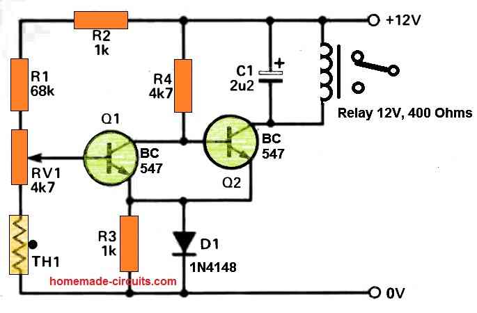
The preset, RV1 enables the working temperature to be established, and is tweaked to make sure that below the preferred cut-off point, the voltage across base of Q2 is adequate to allow it to be in the switched on condition.
As the thermistor temperature increases, the voltage around the base of Q1, which is extracted from the resistive divider network comprising of R1,R2, RV1 and TH1, starts falling, ultimately permitting Q1 to turn off.
The moment Q1 turns off the voltage around the base of Q2 goes up and the relay is switched on.
The diode, D1 delivers temperature compensation to the a pair of transistors, and C1 functions like a back EMF preventer for the relay. As indicated in the diagram, the circuit temperature range could be anywhere around 35 to 100 degrees centigrade.
As long as the relay is in an inactive condition, the current draw of the circuit is very little at around 2 to 3mA. Therefore, the circuit could be powered from either battery packs,or a tiny DC power sources.
Construction
A straightforward circuit which is explained here might be constructed over a tiny PCB. When constructed, the circuit must be two times inspected for proper positioning of diodes, transistors and capacitors, and only after that should be powered ON.
The thermistors possess no built-in polarity, and could therefore be hooked up without worrying about its direction.
How to Set Up
To set up the circuit, adjust the preset RV1 to roughly at the midway, and then slightly heat up the thermistor using some sort of external heating source, for example you can take a light bulb, or a soldering iron in close proximity to the thermistor.
Within a few seconds you should find the the relay clicking ON and any kind of device connected to the relay contacts could be seen switched on.
Next, as soon as the heat source moved away from the thermistor, the thermistor will start cooling down, until its temperature decreases below the trip-point and the relay switches OFF, turning off the connected load.
Applications
The relay output of this temperature controlled relay circuit could be attached to either an alarm device, or any kind of heating system, or cooling system.
For example the circuit could be used for switching ON a cooling fan as soon as the temperature is detected to be beyond a high threshold.
It could used for cooling heatsinks or for cooling semiconductor devices in inverters.
While picking out a appropriate location for the temperature sensor, be cautious to stay away from putting it in a situation where it will likely be exposed to external heating agents.


Questions & Answers
Thanks for the good work.
Please how can this circuit diagram be adjusted to activate the relay at 37.8°C and deactivate it at 37.6°C?
Thanks in anticipation.
It is not possible to get such sharp accuracy from this design.
You might need to modify one of the following circuits, for getting that much accuracy:
https://www.homemade-circuits.com/making-simplest-room-thermometer/
Thanks Swag.
I checked the link you suggested (https://www.homemade-circuits.com/making-simplest-room-thermometer/) and found thermometer projects, but the one I am requesting for should be a thermostat project instead since it switches the relay on and off at different temperatures.
Please, if you can help, I will be very grateful Sir.
Hi Lisbon,
“….activate the relay at 37.8°C and deactivate it at 37.6°C”
These are not two different temperatures, they are almost the same, with a difference of just 0.2 °C, this can be achieved only through an IC based temperature sensor and an opamp based driver.
If you add a relay to one of the thermometer projects then it will do the job exactly as you have specified.
Please build and this design and let me know, then we can add a relay to it afterwards.
Explanation is given in the thermometer article.
Hi. I can solder up a circuit but not able to design one effectively.
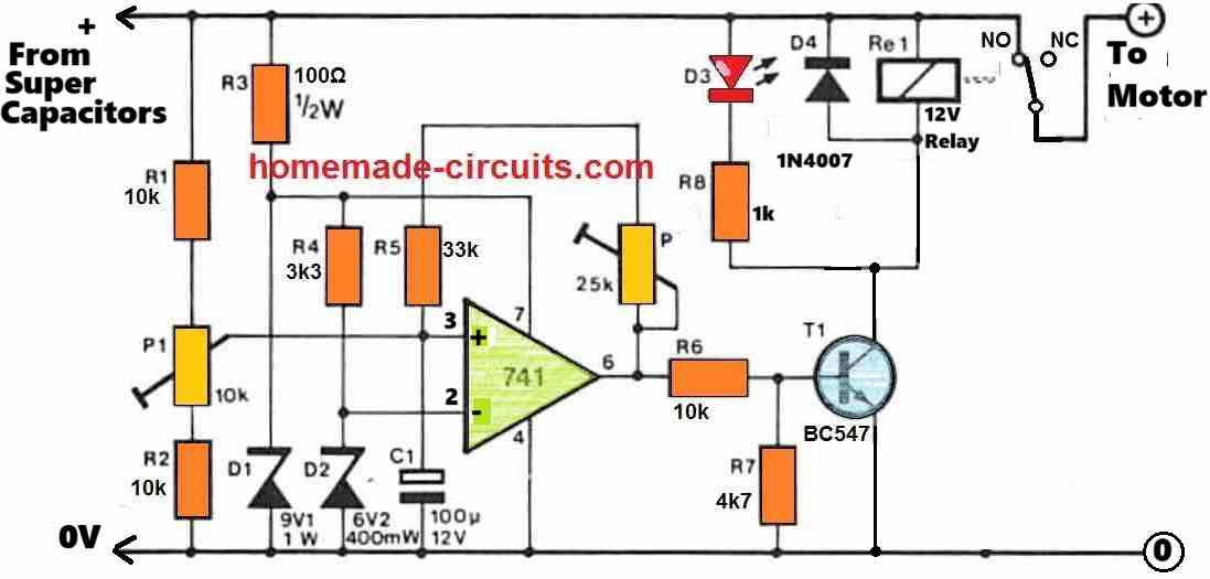
I have a 12V/3A water pump that I am going to use to circulate water from a diy heat panel on the roof to the hws under house. I want to use a supercapacitor to do the heavy lifting driven from a 36V solar panel with a buck converter on it. I want to use a relay that would switch the capacitor ON for the pump when the voltage is, say, 15V and then switch OFF if the voltage drops below, say, 9V. I don’t want to burn the pump motor out with under voltage during dim light hours.
i am guessing that the circuit would be simple but is beyond me. Thank you, in advance. Vic.
I have designed the required circuit, you can view it under the following link. If you have any further questions please feel free to ask.
Swagatam
What a great service you provide! The work you do isn’t work. It is best very best form of play. It must give you great pleasure to use your brilliance to provide solutions to the many problems people have.
Thank you very much.
I will begin gathering components and solder it up. I will let you know how it goes.
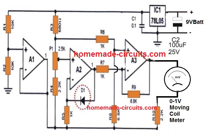
One question. Are D1 and D2 special types of diodes?
Victor
You are most welcome Victor,
D1, D2 are standard zener diodes.
P1 and P2 are presets or trimpots. P2 is connected with pin#6 of the IC.
P1 and P2 can be set in the following manner:
Keep P2 disconnected initially.
Rotate the slider arm of the P1 preset completely towards ground or R2.
Feed 14V or 15V DC from the super-capacitor side. Now, slowly adjust the P1 preset until the relay just clicks ON (D3 is illuminated). If you have problems, try removing R2 and replace it with a short.
Next, connect P2 back and adjust its slider so that its resistance becomes minimum or 0.
Now reduce the 15V DC down to 9V, and adjust P2 again so that the relay just turns OFF (D3 shuts off).
P1, P2 setting may interact with each slightly so you may have to tweak the setting a few times until the right balance is achieved.
The setting up is now complete.
Hi Swagatam
We have had some fine weather so have been in the paddock working. Today was showers so I decided to have some fun with the cct. I played with it in stages so that I could try to understand how it all works and mostly OK. For testing, I am using a 13V battery with a buck as my variable supply and set the upper limit to 12V and lower at 9. Once ON at 12, I slide it down to 9 and it switches OFF – as it should. However, it will not turn on again when I slide it back up to 12+. It only switches on again if I briefly remove the feedback loop and reinsert it and then the cycle repeats. Removing the capacitor had no effect. Any ideas? I will keep playing with it tomorrow as showers again predicted.
Have a great day.
Vic
Thanks Victor,
Yes, the P1, and P2 settings will interact with each other a bit, and therefore the hysteresis will need some extra effort in order to make the cut-offs accurate.
You can do one thing, reduce the R5 33k to 1k and replace the P2 preset with a 100k preset of a 220k preset, this will allow you to get wider range of adjustment for the hysteresis control.
Have a nice weekend.
Hi, I can help you with the circuit design, however there are some confusions.
How is the super capacitor connected with the buck converter output? Are they connected directly with the output of the buck converter or through a relay? And where is the motor supply connected? Once the power is cut off at 9V, the motor should not be switched ON until 15V is reached, is that correct??
According to my understanding, it should be like this: Solar panel output connected to a buck converter, buck converter output connected to the super capacitors, this buck/super-capacitor output supply connected to an opamp circuit for detecting the low voltage at 9V which activates a relay for powering or turning off the motor.
Hello sir I hope you are healthy and well ☺️
Actually I have a issue with is this because sometimes when I use this circuit that you have made for me is getting off without reaching the targeted temperature and some times it’s works fine but at another time after reaching targeted temperature it don’t off ! Relay don’t even switch why ?
Did you understood my point ☝️
Hello Neeraj,
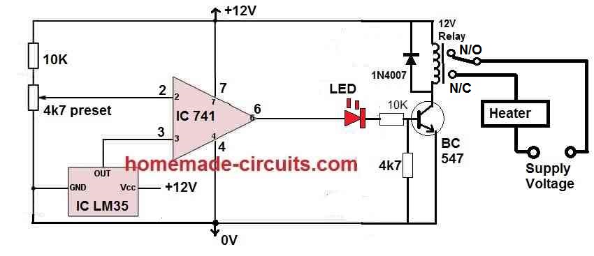
We have already made too many modification in your circuit so it can be difficult for me to understand the issue without practically checking your circuit.
Moreover, thermistors are not so accurate, so if you want more accuracy then you may have too employ an opamp circuit with LM35 IC.
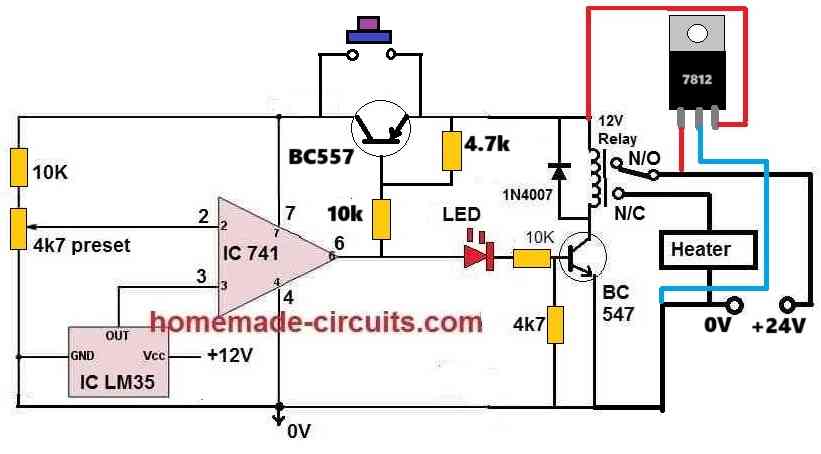
Hey why you didn’t give me earlier! It’s beautiful but how can I add Lm7812 ic?
And what about its efficiency and accuracy?
You can add the 7812 between the +12v input supply and the positive line of the circuit. Meaning, the input of the 7812 will connect with the +12v DC, output of the 7812 will connect with the positive of the circuit, 7812 ground will connect with the ground line of the circuit.
I have a doubt ? I can see the relays connections are wrong! And the input voltage is 24v 15a 360w ! And where is the push button function ? And it will work like the previous circuit? After pressing the push button it will on and after reaching the desired temperature it will cut-off the power !
These are my Little doubts !
You can change relay/heater connections as per your requirement, just check whether the circuit is responding accurately or not.
Sir you are the genius person why don’t you change it ! It gonna make me confused and again I will come back to you again I know it’s a bit quacky! Sorry
What’s about other stuff like push button function and cut off functions ?
Neeraj, You can try the following design:
Okay sir ? i will update you as soon as possible ☺️
OK!!
Sir I got the problem! The 7812 is heating madly and push button function is not working and whole circuit is not working! I double checked everything every connection but still got this issue!
Neeraj,
It will surely work if you do it with proper understanding and in a step by step manner. The setting up procedure is important.
I will update the whole procedure in another article and I will let you know soon.
However, the 7812 heating cannot be eliminated. Therefore i would recommend you to use a 24V relay instead, which will allow the circuit to work directly from 24V DC source without the 7812.
Sir I will try to make it again with proper way and elimination of the 7812 is not needed because 24v relays are so heavy ! I will make this again with proper way ? thanks
Neeraj, 24V relay is not heavy, I would recommend using 24v relay only so that the circuit becomes very simple.
Please do not make the previous circuit, I will make it smaller, so you can try the new modified circuit.
Okay master I will wait for it
I have published it in the following link, you can check it out and if you have questions you can comment under this article.
https://www.homemade-circuits.com/lm35-ic-temperature-controller-circuit-with-push-button/
It will be highly accurate.
Hello sir btw first off all happy new year and I have a problem for you ! So I have tried 5v for the touch module but the whole circuit didn’t worked the temperature sensing function is not working and the touch module also it’s got straight on when connected to the power !
Hello Neeraj,
Happy New Year to you!
I hope you have correctly integrated the following two circuits as per the given suggestions.
Firstly, are two circuits working normally when they are not integrated with each other.
Is the capacitive switch module working OK with the 4.7V zener, 4.7k resistor, from 24V DC input, without the BC557 connection?
Please confirm these.
I have checked then when I connect them to each other and it’s works finely no issues but after that I bought lm7805 and added to the main temperature circuit in the circuit was working but the functions were not quite good after that I connect capacitive touch module with direct bc557 and it didn’t work as it should be ! Thats my issue your capacitive circuit worked super efficiently!
Then don’t use 7805, use 7812 for the temperature sensor circuit…
But I don’t wanna use another circuit for capacitive touch module ! Isn’t there any other way ! ☹️
You will have to add the extra parts on the ttp223 as shown in the previous linked diagram, there is no other option.
Hello, good morning, first of all, happy new year 2024. I just need this circuit, but on the contrary… I mean, when the temperature rises beyond a certain value, the relay must be disconnected, turned off… Thank you very much. Best regards from Italy ??
Happy New Year to You! I think you can replace R1 with the Thermistor, and replace the existing Thermistor point with a short, then it will do exactly as per your specifications.