One of the best substitutes for traditional light transformer for halogen bulbs is the electronic halogen transformer. It can also be used with non-halogen bulbs and any other form of resistive loads that does not run on RF current.
Written and Submitted By: Dhrubajyoti Biswas

Halogen Lamp Working Principle
The electronic halogen lamp transformer works on the principle of switching power supply. It does not run on secondary rectifier like the switching power supply, for which DC voltage is not needed to run the same.
Moreover, it doesn’t have the option of smoothing after network bridge and it is simply due to the absence of electrolyte the application of thermistor does not come in application.
Eliminating Power Factor Issue
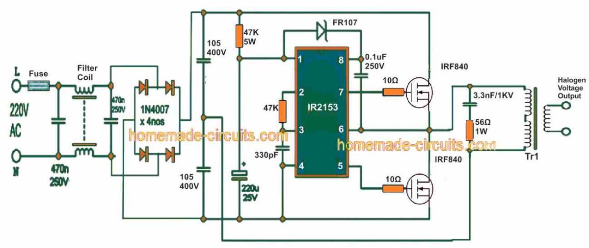
The design of the electronic halogen transformer also eliminates the issue with power factor. Designed with MOSFET as a half-bridge and IR2153 driving circuit, the circuit is equipped with upper MOSFET driver and also has its own RC oscillator.
The transformer circuit runs on a frequency of 50 kHz and the voltage is around 107V at the primary pulse transformer, which is measured as per the following calculation mentioned below:
Uef = (Uvst-2) . 0,5 . √(t-2.deadtime)/t
[Here Uvst is the input line voltage and the resulting dead-time in IR2153 is set to 1. The value 2us and t is stated as the period and especially in regard to 50 kHz.].
However, upon substituting the value with the formula: U = (230-2) . 0,5 . √(20-2.1,2)/20 = 106,9V, the voltage gets reduced by 2V at the diode bridge. It is further subdivided by 2 at the capacitive divider, which is made of 1u/250V capacitors, thus reducing the effective value at dead-time.
Designing the Ferrite Transformer
The Tr1 transformer on the other hand is a pulse transformer placed on ferrite core of either EE or E1 can be lent from SMPS [AT or ATX].
While designing the circuit, it is important to bear in mind that the core should maintain a cross section of 90 – 140mm2 (approx.). Furthermore, the number of turns also has to be adjusted with based upon the state of the bulb. When we try to determine the calculation of transformer rate, we usually take it for consideration that the primary rate is the effective voltage of 107V in case of 230V output line.
The transformer derived from AT or ATX generally gives 40 turns on primary and is further sub-divided into two parts having 20 turns on each primary – one that lies under the secondary while the other above the same. In case if you are using 12V, I would recommend using 4 turns and the voltage should be 11.5V.
For your note, the transformation ratio is calculated with a simple division method: 107V / 11.5 V = 9.304. Also in the secondary section, the value is 4t, so the primary value should be: 9.304 . 4t = 37t. However, since the bottom half of the primary remains in 20z, the best option would be wind the top layer by 37t - 20t = 17t.
And if you can trace out the original number of turns in secondary, things will be far easier for you. If the secondary is set to 4 turns just unwind 3 turns from the top of the primary to derive the result. One of the simplest procedures for this experiment is using 24V bulb, albeit the secondary to choose should be 8-10 turns.
The IRF840 or STP9NK50Z MOSFET without the absence of heat sink can be applied to derive the output of 80 – 100V (approx.).
The other option would be use STP9NC60FP, STP11NK50Z or STP10NK60Z MOSFET model. In case if you are looking to add more power, do use heat sink or MOSFET with higher power, such as 2SK2837, STB25NM50N-1, STP25NM50N, STW20NK50Z, STP15NK50ZFP, IRFP460LC or IRFP460. Be sure to consider that the voltage should be Uds 500 – 600V.
Care should also be taken, not to have a long lead to the bulb. The main reason is, in case of high voltage it may result to drop of voltage and cause interference mainly due to inductance. One last point to consider you can’t measure the voltage with the help of multimeter.


Questions & Answers
Sir with this circuit how much load in terms of watt can be safely used or connected
Hi Shantanu, The circuit should be able to handle 50 watts comfortably.
Sir with this circuit after full bridge rectifier diode can we use to drive a 24 volt DC ro pump
Shatanu, after the bridge rectifier it will be around 310V, so it cannot be used to drive a 24v load….
Sir I meant to connect a bridge rectifier with high speed diode on the secondary side of the SMPS transformer where we connect the 24 volt halogen lamp
Yes, that is possible, you can connect a 24V motor at the secondary side after a bridge rectifier.
Please explain to me the pre amplification stage of an amplifier
Dear sir,
Please give me details of filter. Types and capacity of filter
Dear Nrupesh, the coils are 35mH each, wound over a ferrite ring type core.
Sir,
I have use this for flyback driver. It is very good. But in some time mosfet have burn out. Please give me circuit for protection of mosfet. I have used IRFP460 mosfet.
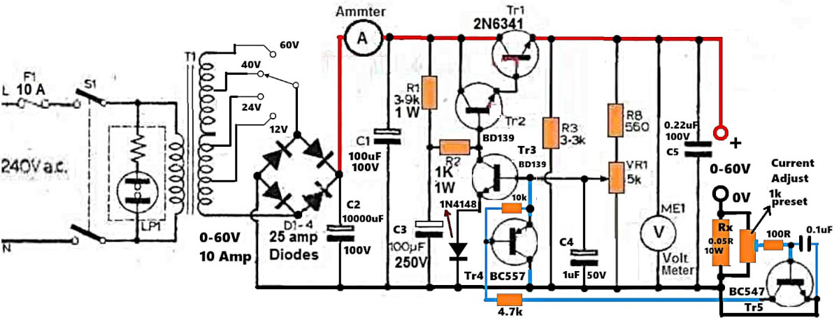
Rupesh, Glad you could make it successfully. The burning of mosfet could be due to voltage fluctuations and over current situation. You can try the current controller concept shown in the following example diagram:
https://www.homemade-circuits.com/wp-content/uploads/2020/06/smps-current-control-add.jpg
The Rx resistor should be 3 times less than the MOSFET max ID rating
Dear Sir,
i am mechanical engineer. I have make for my hobby. So i haven’t more knowledge of electronics. I have use IRFP460 mosfet and two capacitors are 470uf/450v. Please sugest me Watt of 150k resistors, voltage of 2.2uf capacitor and value of RX. This is my request sir.
Dear Nrupesh, the above SMPS circuit is recommended only for expert electronic engineers, so you may find the modifications a bit difficult.
Please add the BC547, and Rx in the halogen lamp circuit as exactly shown in the linked circuit in my previous email.
sir this circuit can i use for battry charging purpuse.
or some need for modification
Dear sir,
Is possible isolated gate transformer in this circuit?
Hello Nrupesh, that can make the design quite complex, so I won’t recommend it.
Prashant, it can be used for battery charging also, but the output voltage will vary with the input voltage, so that can be a problem.
When i connected pin 6 to ground then i was able to measure frequency at pin 5 & grond also pin 7 and ground. Also between pin 5 and 7.
The problem was when i leave pin 6 disconnected frequency was not stable. but changing very rapidly. After connecting pin 6 to ground i am able to measure frequency.
Thank you sir.
OK, but that's not the right procedure. pin#6 is the output of the IC and should never be connected to ground. I think there could be some other issue which may be causing instability for the IC.
its not showing up reading 🙁
then your IC is not oscillating…try measuring it at pin#5 and ground
Sir,
can you help me to find frequency of IR2153?
How can i measure frequency of IR2153 circuit?
I have UNI-T frequency meter but i don't know how to measure frequency?
Do i need to put transistors and load on IR2153 ic or not to measure frequency?
Please provide circuit diagram if possible.
Thanks
…I mean you can measure it across the 330pF capacitor…
Muhammad, you can measure the frequency it across "Ct"