• Skip to main content
  • Skip to primary sidebar

Homemade Circuit Projects

Get free circuit help 24/7

New Projects | Privacy Policy | About us | Contact | Disclaimer | Copyright | Videos 

You are here: Home / Mini Projects / Simple Water Heater Alarm Circuit

Simple Water Heater Alarm Circuit

Last Updated on March 1, 2023 by Swagatam 1 Comment

The post explains a simple water heater alarm circuit which may be used as a safety device for getting indications regarding the switched position of a water heater or a geyser through intermittent buzzer actuation. The idea was requested by Mr. Mathew.

Technical Specifications

To be frank i am new to your blog https://www.homemade-circuits.com

I was googling on how to make a reminder alarm for my water heater that i forget every time to switch off.

I would be lot grateful if you could give me a circuit diagram through your website on how to make it.

I am sure it would be beneficial for most of the people who gets into trouble with geyser switched on for long periods.

Looking for a piezzo buzzer circuit that sounds every one minute (adjustable) interval for a certain milliseconds or say one second (adjustable preferably again).
Hope your helping hand would guide me.
Regards

Mathew Joy

The Design

The proposed water heater alarm circuit functioning can be studied by referring to the following discussion and the diagram:

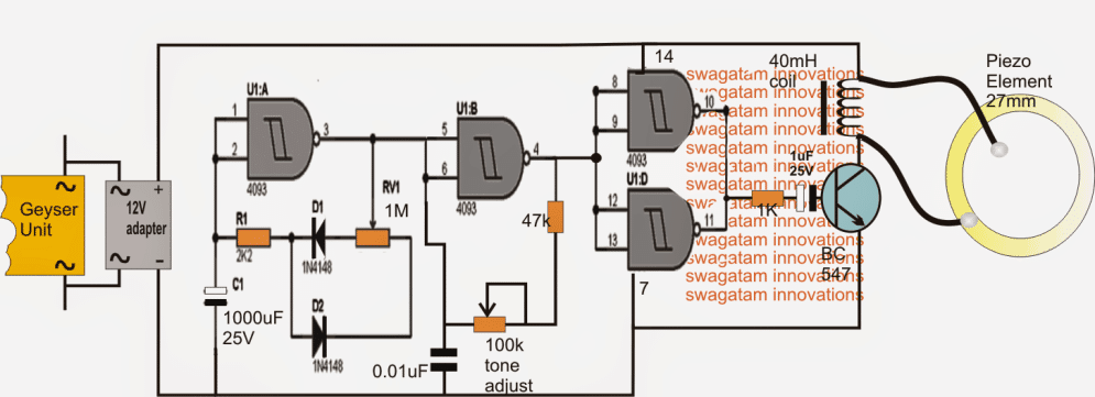
A single IC 4093 which is a quad Schmidt NAND gate IC is used here for executing two operations simultaneously viz for generating the timing pulses and the for generating the buzzer frequency.

As may be witnessed in the given diagram, the design can be divided into three basic stages, where U1A forms the PWM timer pulse generator stage, U1B becomes responsible for creating the buzzer frequency while the remaining two gates are used as buffers for delivering the U1B frequency output to the transistor/piezo buzzer network.

When the heater is first switched ON, the circuit also actuates wherein C1 grounds the input of U1A rendering a high at its output which in turn keeps the U1B disabled from making the buzzer frequency.

With the above situation the buzzer stays silent for the moment until C1 charges via R1, D1, RV1 and via the high logic from the output pin3 of the IC.

Delay Period Adjust using PWM

The delay period may be predetermined by suitably adjusting the duty cycle of the stage through RV1 (here it is intended to be 1 minute OFF and 2 sec ON)

A soon as this happens, a logic high appears at the input pin1/2 of the IC which instantly flips the output of U1A, enabling the U1B which now begins generating the required buzzer frequency, but only until C1 yet again discharges completely via R1, D2, RV1 and via the zero logic at pin3, the situation now reverts to the previous situation and continues repeating the procedures infinitely until the geyser is switched OFF.

This frequency is further buffered and transferred via U1D gates to the transistor buzzer driver stage which sounds the connected buzzer/coil assembly generating an ear piercing audible sound, indicating that the heater or the geyser is in the switched ON position and may be needs an attention

Circuit Diagram

caution electricity can be dangerous

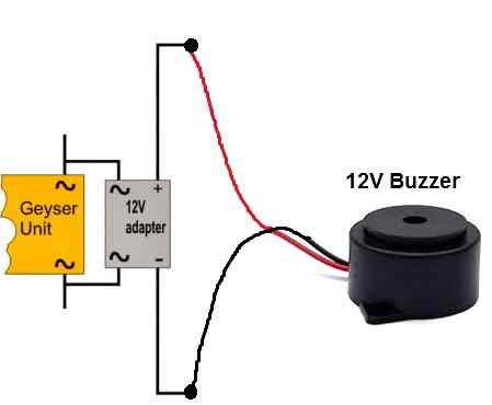
You can simply connect a ready made buzzer with the adapter in the following manner:

You'll also like:

  • 1.  5 KVA to 10 KVA Automatic Voltage Stabilizer – 220 Volts, 120 Volts
  • 2.  Simple RGB LED Controller Circuit
  • 3.  Transistor Monostable Circuits with Applications
  • 4.  4 Simple Power Bank Circuits for Mobile Phones
  • 5.  Simple 50 Watt Power Amplifier Circuit
  • 6.  4 Simple Proximity Sensor Circuits – Using IC LM358, IC LM567, IC 555

About Swagatam

I am an electronic engineer (dipIETE ), hobbyist, inventor, schematic/PCB designer, manufacturer. I am also the founder of the website: https://www.homemade-circuits.com/, where I love sharing my innovative circuit ideas and tutorials.
If you have any circuit related query, you may interact through comments, I'll be most happy to help!

Have Questions? Please Comment below to Solve your Queries! Comments must be Related to the above Topic!!

Subscribe
Notify of
1 Comment
Newest
Oldest
Inline Feedbacks
View all comments

Primary Sidebar

Categories

  • 3-Phase Power (15)
  • 324 IC Circuits (19)
  • 4017 IC Circuits (52)
  • 4060 IC Circuits (26)
  • 555 IC Circuits (99)
  • 741 IC Circuits (20)
  • Arduino Engineering Projects (83)
  • Audio and Amplifier Projects (115)
  • Battery Chargers (83)
  • Car and Motorcycle (95)
  • Datasheets (74)
  • Decorative Lighting (Diwali, Christmas) (33)
  • Electronic Components (101)
  • Electronic Devices and Circuit Theory (36)
  • Electronics Tutorial (120)
  • Fish Aquarium (5)
  • Free Energy (34)
  • Fun Projects (13)
  • GSM Projects (9)
  • Health Related (20)
  • Heater Controllers (29)
  • Home Electrical Circuits (104)
  • How to Articles (20)
  • Incubator Related (6)
  • Industrial Electronics (28)
  • Infrared (IR) (40)
  • Inverter Circuits (98)
  • Laser Projects (12)
  • LED and Light Effect (93)
  • LM317/LM338 (21)
  • LM3915 IC (25)
  • Meters and Testers (66)
  • Mini Projects (150)
  • Motor Controller (67)
  • MPPT (7)
  • Oscillator Circuits (26)
  • PIR (Passive Infrared) (8)
  • Power Electronics (34)
  • Power Supply Circuits (79)
  • Radio Circuits (10)
  • Remote Control (48)
  • Security and Alarm (62)
  • Sensors and Detectors (121)
  • SG3525 IC (5)
  • Simple Circuits (75)
  • SMPS (29)
  • Solar Controllers (61)
  • Timer and Delay Relay (53)
  • TL494 IC (5)
  • Transformerless Power Supply (8)
  • Transmitter Circuits (41)
  • Ultrasonic Projects (16)
  • Water Level Controller (45)

Calculators

  • AWG to Millimeter Converter
  • Battery Back up Time Calculator
  • Capacitance Reactance Calculator
  • IC 555 Astable Calculator
  • IC 555 Monostable Calculator
  • Inductance Calculator
  • LC Resonance Calculator
  • LM317, LM338, LM396 Calculator
  • Ohm’s Law Calculator
  • Phase Angle Phase Shift Calculator
  • Power Factor (PF) Calculator
  • Reactance Calculator
  • Small Signal Transistor(BJT) and Diode Quick Datasheet
  • Transistor Astable Calculator
  • Transistor base Resistor Calculator
  • Voltage Divider Calculator
  • Wire Current Calculator
  • Zener Diode Calculator

© 2023 · Swagatam Innovations

wpDiscuz