In this article I have explained a simple low dropout LDO, or zero drop solar charger circuit without microcontroller which can be modified in many different ways as per user preference. The circuit does not depend on microcontroller and can be built even by a layman.
What is a Zero Drop Charger
A zero drop solar charger is a device which ensures that the voltage from the solar panel reaches the battery without undergoing any drop in voltage, either due to resistance or semiconductor interference.
The circuit here uses a MOSFET as a switch for ensuring minimum drop in voltage from the attached solar panel.
Moreover the circuit has a distinct advantage over other forms of zero drop charger designs, it does not unnecessarily shunt the panel making sure the panel is allowed to operate at its highest efficiency zone.
So I have explained how these features could be achieved through this novel circuit idea designed by me.
Simplest LDO Circuit
Here's a simplest LDO solar charger example which can be built in minutes, by any interested hobbyist.
These circuits can be effectively used in place of expensive Schottky diodes, for getting an equivalent zero drop transfer of solar energy to the load.
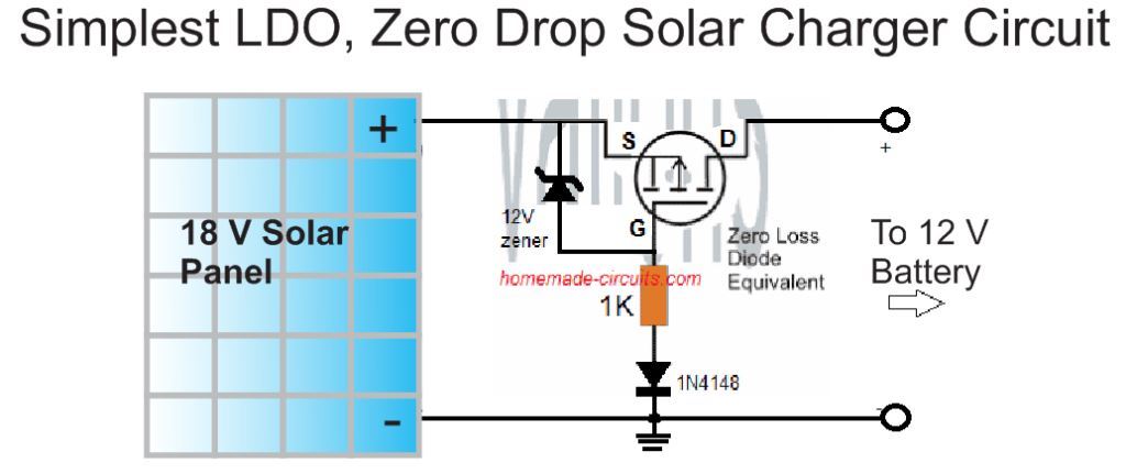
A P channel MOSFET is used as a zero drop LDO switch. The zener diode protects the MOSFET from high solar panel voltages above 20 V. The 1N4148 protects the MOSFET from a reverse solar panel connection.
Thus, this MOSFET LDO becomes fully protected from reverse polarity conditions and also allows the battery to charge without dropping any voltage in the middle.
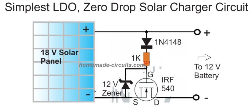
For an N-channel version you can try the following variant.
Using Op Amps
If you are interested to build a zero drop charger with automatic cut off feature, you can apply this using an op amp is wired as a comparator as shown below.
In this design the non-inverting pin of the IC is positioned as the voltage sensor via a voltage divider stage made by R3 and R4.
Referring to the proposed zero drop voltage regulator charger circuit diagram we see a rather straightforward configuration consisting of an opamp and a mosfet as the main active ingredients.
The inverting pin is as usual rigged as the reference input using R2 and the zener diode.
Assuming the battery to be charged is a 12V battery, the junction between R3 and R4 is calculated such that it produces 14.4V at a certain optimal input voltage level which may be the open circuit voltage of the connected panel.
On applying the solar voltage at the shown input terminals, the mosfet initiates with the help of R1 and allows the entire voltage across its drain lead which finally reaches the R3/R4 junction.
The voltage level is instantly sensed here and if in case it's higher than the set 14.4V, switches ON the opamp output to a high potential.
This action instantly switches OFF the mosfet making sure no further voltage is allowed to reach its drain.
However in the process the voltage now tends to fall below the 14.4V mark across the R3/R4 junction which yet again prompts the opamp output to go low and in turn switch ON the mosfet.
The above switching goes on repeating rapidly which results in a constant 14.4V at the output fed to the battery terminals.
The use of the mosfet ensures an almost zero drop output from the solar panel.
D1/C1 are introduced for maintaining and sustaining a constant supply to the IC supply pins.
Unlike shunt type regulators, here the excess voltage from the solar panel is controlled by switching OFF the panel, which ensures zero loading of the solar panel and allows it to operate at its most efficient conditions, quite like an MPPT situation.
The LDO solar charger circuit without microcontroller can be easily upgraded by adding an auto cut off, and an over current limit features.
Circuit Diagram
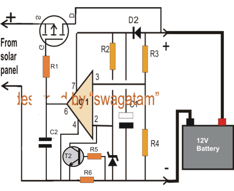
NOTE: PLEASE CONNECT THE PIN#7 OF THE IC DIRECTLY WITH THE (+)TERMINAL OF THE SOLAR PANEL OTHERWISE THE CIRCUIT WILL NOT FUNCTION. USE LM321 IF THE SOLAR PANEL VOLTAGE IS HIGHER THAN 18 V.
Parts List
- R1,R2 = 10K
- R3,R4 = use an online potential divider calculator for fixing the required junction voltage
- D2 = 1N4148
- C1 = 10uF/50V
- C2 = 0.22uF
- Z1 = should be much lower than the selected battery over charge level
- IC1 = 741
- Mosfet = as per the battery AH and the solar voltage.
Using N-Channel MOSFET
The proposed low dropout can be also effectively implemented using an N-channel MOSFET. as indicated below:
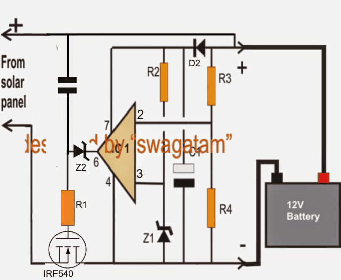
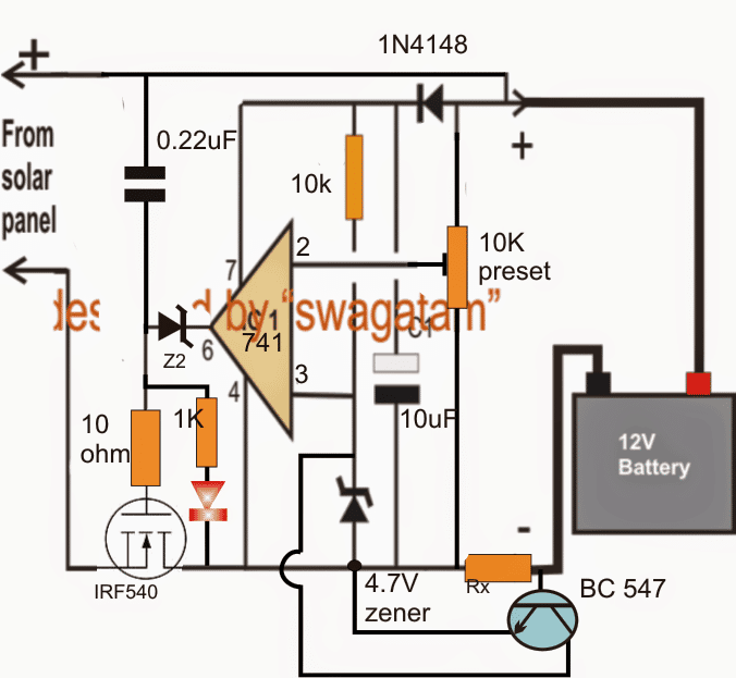
NOTE: PLEASE CONNECT THE PIN#4 OF THE IC DIRECTLY WITH THE (-)TERMINAL OF THE SOLAR PANEL, OTHERWISE THE CIRCUIT WILL CEASE TO WORK. USE LM321 INSTEAD OF 741 IF THE PANEL OUTPUT IS HIGHER THAN 18 V.
Adding a Current Control Feature
The second diagram above shows how the above the design may be upgraded with a current control feature by simply adding a BC547 transistor stage across the inverting input of the opamp.
R5 can be any low value resistor such as a 100 ohm.
R6 determines the maximum allowable charging current to the battery which may be set by using the formula:
R(Ohms) = 0.6/I, where I is the optimal charging rate (amps) of the connected battery.
Finalized Solar zero drop battery charger circuit:
As per the suggestion of "jrp4d"the above explained designs needed some serious modifications for operating correctly. I have presented the finalized, corrected working designs for the same through the below shown diagrams:
According to "jrp4d":
Hi - I've been messing about with Mosfets (voltage control circuits) and I don't think either circuit will work except where the line in voltage is only a few volts large than the target battery voltage. For anything where the line in is much more than the battery the mosfet will just conduct because the control circuit can't control it.
In both circuits its the same problem, with P-channel the op-amp cant drive the gate high enough to turn it off (as observed by one post) - it just passes the line voltage straight thru to the battery. In the N channel version the op-amp can't drive the gate low enough because its operating at a higher voltage than the -ve line in side.
Both circuits need a driving device operating at the full line in voltage, controlled by the op-amp
The suggestion above looks valid and correct. The simplest way to rectify the above problem is to connect Pin#7 of the opamp IC with the (+) of the solar panel directly. This would instantly solve the issue!
Alternatively the above designs could be modified in the manner shown below for the same:
Using NPN BJT or N-channel mosfet:
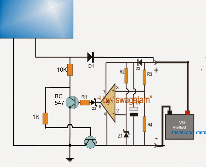
In the above figure the NPN power transistor could be a TIP142, or a IRF540 mosfet .....and please Remove D1 as it's simply not required.
Parts List
- R1, R2 = 10 K
- R3, R4 = use an online potential divider calculator for fixing the required junction voltage
- D2 = 1N4148
- C1 = 10 uF / 50 V
- C2 = 0.22 uF
- Z1 = should be much lower than the selected battery over charge level
- IC1 = IC 741
- Lower Transistor = TIP142 or as per the battery Ah and the solar voltage.
Using PNP transistor or P-mosfet
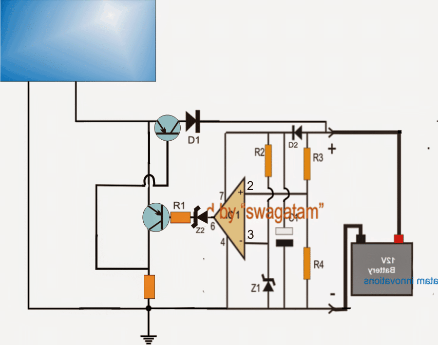
In the above figure, the power transistor could be a TIP147 or a IRF9540 mosfet, the transistor associated with R1 could be a BC557 transistor......and please Remove D1 as it's simply not required.
How to Set up the LDO solar charger circuit
It's very easy.
- Do not connect any supply at the mosfet side.
- Replace the battery with a variable power supply input and adjust it to the charging level of the battery which is supposed to be charged.
- Now carefully adjust the pin2 preset until the LED just shuts off....flick the preset to and fro and check the LED response it should also blink ON/OFF correspondingly, finally adjust the preset to a point where the LeD just shuts off completely....seal the preset.
- Your zero drop solar charger is ready, and set.
You can confirm the above by applying a much higher input voltage at the mosfet side, you'll find the battery side output producing the perfectly regulated voltage level that was previously set by you.



Questions & Answers
Hi Sir,
I have a 12V, 130AH battery and a solar panel of 24V 150W.
How do I calculate R3 and R4 ?? Also please help for the value
of Z1 and mosfet ratings.
Thank you in advance.
Rashid
Hi Rashid,
Use an online voltage divider calculator for determining the values of R3/R4 such that it's junction gives 14.4V at 15V input.
Set it with a ac/dc power supply in place of the solar panel, means after this anything above 15V will be appropriately controlled as explained in the article.
i m tapas
where i will found solar plates…
good day! presently solar panels will be costly no matter from where you buy it.
I have no idea regarding exact shops who are specialized in the PV field.
You can try ordering it online from any chinese vendor as they are quite competitive.
you can use a BJT (transistor) in place of mosfet, relay will not work.
p-channel
it's for enabling the mosfet to start conducting, without it the circuit will never initiate when switched ON.
It's mosfet gate drive resistor
A mosfet requires a voltage across its gate and source in order to conduct, positive for N-channel and negative for P-channel
here the P-channel acquires a negative potential via the shown resistor for conducting. It can be replaced with a short still the mosfet would work but the positive from the opamp would get shorted to ground getting damaged, that's why the resistor is included specifically.
When the opamp output goes high it generates a positive potential at the gate and cuts off the negative drive such that the mosfet shuts off and process continues as explained in the article.
You can refer any online source for knowing how mosfets work in details.
as expressed in the above comment, inclusion or elimination of resistor does not produce any affect in mosfet gate triggering.
Z1 can be a 4.7V zener, current limit can be easily included by adding a transistor stage, will try to update it soon.
The zener can be a 6V zener,
10k for R3, and 10K preset for R4. Adjust R4 until you get exactly 15V at the output.
If its voltage and current ratings are as per your battery charging rate then it is OK.
yes you can use the above circuit for that purpose.
Hi Swag,
pls i would want to use an nmos instead of pmos in the circuit . How could tha be done ?
Tmx.
Hi Kassim,
You can try swapping the pin2/3 with each other for an nmos at the output.
Dear Swagatam Sir,
I have 150 w Panel with VoC : 21 V and IoC :6.5 in peak conditions and Battery to be charged is 12 V , 100 AH .
Can you help me in determining values of R3, R4 , Zener Diode No. , and MOSFET No. so that I can procure them .
Best Regards.
MANISH VISHWAKARMA
Hyderabad
Dear Swagatam Sir,
I have a 150 w solar panel with VoC = 21 V and IoC = 6.7 A ,
I need to charge 12 v – 100 AH battery
can you help me in determining values of R3 , R4 , Zener Diode No , Mosfet No . & R6 .
I can procure them along with the Other material and start this project .
best regards.
MANISH
Dear <anish,
You will need a 15amp solar panel for charging a 100AH battery.
You can use IRf9540 mosfet
zener can be 6V, 1/2 watt
R3 = 4.7k
R4 = 20k
Swagatam, good circuit. It seems that you don1t know what mppt cgarging really is. This charger defenently isn`t. For mppt ypu need an inductor and electronics which wont allow PV module voltage to drop below 17.5v +_ 0.5.
Thanks Vladimir,
I have understood MPPT better than anybody else that's why I am trying to prove that it does not have to be all that complex…..and can be implemented by simpler means, although that would come with a few compromises and limitations which are no big deal.
Please read my other articles about MPPT, you will get an idea regarding my knowledge about it.
If you have personal queries about MPPT feel free to ask them here.
hi Swag
pin 3(ic 741) calcular:Vbb=((R3+R4)*Vcc)/R3*R4 is valid over charger
is Z1 valid begin charger
Hi Khang,
I have not yet confirmed this formula so canot say about it.
In the above diagram Z1 and R3/R4 form a valid overcut configuration
Hi Swag
sorry, formular wrong . but i think circuits not work because mosfet p channel work in negative voltage.pin 4( ic 741) connection 0V(mass) . mosfet cant's work . currents charger very low.I 'm check in actual
Thank's
Hi khang, the 741 will produce negative voltage….. please go through the circuit explanation.
Hi Sir
that is 741 use comparator circuit.741 use dual volte(+vcc and -vcc).you connect pin 4 in 0v .it cant's produce negative voltage.
Hi khang,
here negative refers to zero volt.
HI Sir
I built your circuit design. circuit is limited by the charging line. I choose z1 = 6V, R3 = 3.9k R4 = 10k but the charge under 1A . DC in 10A 20V, 100AH battery.
Can you guide me
Thanks
Hi khang,
disconnect pin7 of the IC from the shown position and provide the supply directly from the 20V input but through a 7812 IC and check the response.
for a 12V batery the output voltage from the circuit should be set at 14.4v
Hi Swaga
How?formular calcula
it's a standard rule.
sir me bhanu actually my problem is I am using here a N-channel mosfet that is IRFZ44N can it be used here…Thank you sir plz help me sir in this….
bhanu, an n channel cannot be used in the above design, it'll require many changes for that
mosfet is not compulsory here, you can use a BJT such as a TIP127 in place of the mosfet
sir swagatam good day
is it possible to add leds to identify solar panel working and to identify the charging status? where shall i put it? thanks again
Aureliano, the above charger does not include a cut-off circuit, so indicators cannot be used here.
you can use an ammeter and put it in series with the battery positive, when it becomes zero would indicate a full battery
for solar panel working indication you can put an LED across pin6 and ground of the IC via a 10k resistor.
Thank you Sir me bhanu…..
actually TIP 127 is not available but can i use IRF9530 or IRF9540 as i am using 12v 1.3Ah battery for charging…
Sir one more problem i am facing i know you have told that the BC547 is used here for current control, I just cant' understand how it functions…please sir help me….
I am not getting a clear description from the note…
Sir can i use R3 as 10k and R4 as 10 preset as according to comments posted by u…
Thank you sir…..
Bhanu, yes any P-channel mosfet will work here.
when excess current flows, the base resistor of BC547 develops a triggering voltage for the BC547 which pulls pin2 of the IC to ground, which in turn instantly makes the output of the IC high deactivating the mosfet and switching it off at that instant, the cycle continues keeping the current within the required limit.
hi sir
dc input is mppt
use dc in trafo is ok?
I need these with input of 20v to 40v with an output of 17.5v @ 40amps. Even if a few are in parallel its okay.
Efficiency should be greater than 90%
Kumar
srestimarketing@gmail.com
The above circuit will work for both the inputs.
use an appropriate preset for R4 for getting the desired output voltage
Hello Sir,
Can I use this circuit for 6V/4.5AH Battery. What will be the changes required? Secondly, can I apply say 9V DC at the input in case no solar power available? Thanks.
hello vb,
no changes would be required, you can use the same circuit.
Hi
Can you please give me some alternatives for IC1 741?
Thanks
you can try IC 301, 318, 709, CA3130, 3140, LF355/356/357, TL071/081 etc
Hi Swagatam.
This looks like a pretty good circuit.
Thank you both for providing the circuit and answering all those questions.
I've learned a lot from what might sound like silly questions (but I think they aren't).
I'd like to interface an ARM microcontroller to my solar panel.
The microcontroller's job would be to measure the voltage using a resistor voltage divider connected to an ADC pin.
As the ARM microcontroller runs at voltages below 3.3V, I need to regulate the voltage, but I do not want to use a 7812 and a 7805, because they'd use a lot of power.
This is why I started to search for better regulators.
I believe that I could use this as a regulator (and a similar circuit for charging a battery).
My ARM device would then transmit the voltage whenever it changes (max. once per second) via a wireless connection, so a receiving chip would store the results for graphical display.
I could also measure the charge currents.
Without load, my 5W panel gives max. 22.4V; it's intended to be used for charging a 12V battery.
I'd like to ask how low the regulator circuit can go, because I do not yet have all the components required to create the circuit (still waiting for the LM741 / UA741).
Would any Mosfet do; eg. the IRF9530 or IRF9540, for a low voltage like 3.3V ?
(I have a TSM2307 P-channel Mosfet as well, which I would prefer if possible: VDS = -30V max, VGS = +/- 20V max, ID = -3A max, RDS(on) = max. 80…140 mOhm).
As you write… "should be lower than the selected battery over charge level", I believe that the zener can be anything above my microcontroller's minimum voltage level (for instance 1.8V, as the microcontroller's voltage range is 1.8V to 3.6V) ?
Thanks Pacman,
Your problem can be simply solved by using the following circuit, the above circuit is way too complex considering the small voltage level you intend to control.
https://www.homemade-circuits.com/2012/08/simplest-dc-cell-phone-charger-circuit.html
Use a 10k resistor instead of the shown 220 ohms, and use a 3.3V zener in place of the existing zener value.
The output of the circuit then could be directly integrated with your ARM MCU.
I am sure this will work better and be much easier for you to implement.
..for the TIP122, you can use a 2N2222 or an 8050
Hi Swagatam.
This was exactly what I needed.
I had some idea that it was possible, I just couldn't spot it. 🙂
I have the zener and resistor; and placed an order with the 2N2222 and a SMT version of it in addition.
The ARM microcontroller (NXP LPC1114) only uses around 9mA, when constantly busy at full speed.
So it looks like there will be plenty of current left over, even after the RF-chip have been consuming its part. 😉
You're absolutely a genious and a great teacher!
I learn a lot from looking at your circuits and trying to follow them.
I hope that I can return the favour one day. =)
(I hope I didn't post this twice; my previous attempt was lost; it seems it's a good idea to copy to the clipboard just before pressing "Publish").
Thanks Pacman, it's my pleasure!!
If 9mA is only that you need then may be just a zener diode with a series resistor would simply do the job….but a zener/resistor config would dissipate some unnecessary energy which could be undesirable….
I have read your other comment will be answering it shortly:-)